Rotigel 1 - Comprehensive Assembly Plan And Visual Guide
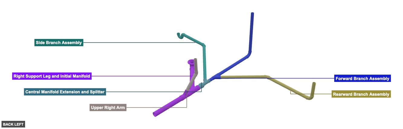
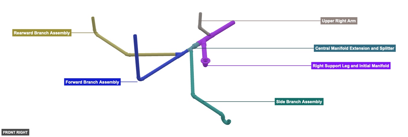
A multi-branched PVC pipe structure, likely for a custom fluid handling system or a specialized frame. It features a main manifold on the right side with several extending arms and branches, constructed using various PVC tubes, wyes, elbows, and specialized fittings like a P-Trap and a Closet Flange. The assembly appears to grow from an initial right-side structure towards the left and forward. - Complex PVC Pipe Assembly
Phase 1: Group Overview
Angle: back left

Right Support Leg and Initial Manifold
 3" Tube PVC DWV x 25"x 1
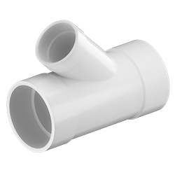 3" x 2" 45° Wye Hub PVC DWV x 1
3" Tube PVC DWV x 3"x 1  3" 45° Wye Hub PVC DWV x 1
3" Tube PVC DWV x 24"x 1 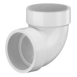 3" 90° Vent Elbow H x H PVC DWVx 1
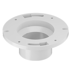 4" x 3" Closet Flange Spg PVC DWVx 1
Upper Right Arm
 2" Tube PVC x 14.34"x 1
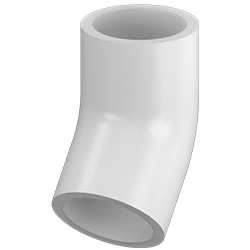 2" 45° Elbow Slip PVCx 1
2" Tube PVC x 12"x 1 Central Manifold Extension and Splitter
3" Tube PVC DWV x 6"x 1 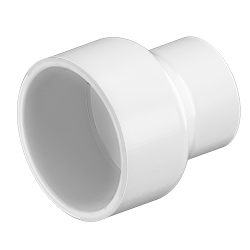 3" x 2" Bell Reducer Slip PVC DWVx 1
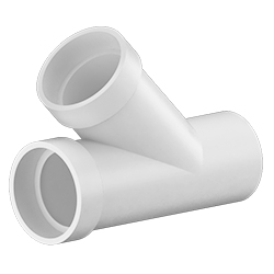 2" Street Wye Spg x H x H PVC DWV x 1
Forward Branch Assembly
2" Tube PVC x 6"x 1 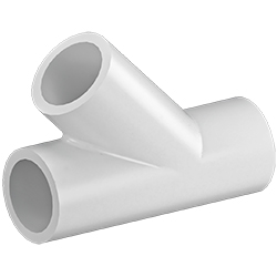 2" Wye Slip PVCx 1
2" Tube PVC x 36"x 2 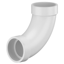 2" 90° Long Turn Elbow H x H PVC DWVx 1
Side Branch Assembly
2" Tube PVC x 48"x 1 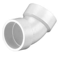 2" 45° Elbow H x H PVC DWVx 1
2" Tube PVC x 24"x 1 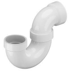 2" P-Trap Hub x Hub - PVC DWVx 1
Rearward Branch Assembly
2" Tube PVC x 36"x 2 2" 45° Elbow H x H PVC DWVx 1 2" Tube PVC x 12"x 1 2" 90° Long Turn Elbow H x H PVC DWVx 1
Angle: front right
Right Support Leg and Initial Manifold
3" Tube PVC DWV x 25"x 1 3" x 2" 45° Wye Hub PVC DWV x 1 3" Tube PVC DWV x 3"x 1 3" 45° Wye Hub PVC DWV x 1 3" Tube PVC DWV x 24"x 1 3" 90° Vent Elbow H x H PVC DWVx 1 4" x 3" Closet Flange Spg PVC DWVx 1 Upper Right Arm
2" Tube PVC x 14.34"x 1 2" 45° Elbow Slip PVCx 1 2" Tube PVC x 12"x 1 Central Manifold Extension and Splitter
3" Tube PVC DWV x 6"x 1 3" x 2" Bell Reducer Slip PVC DWVx 1 2" Street Wye Spg x H x H PVC DWV x 1 Forward Branch Assembly
2" Tube PVC x 6"x 1 2" Wye Slip PVCx 1 2" Tube PVC x 36"x 2 2" 90° Long Turn Elbow H x H PVC DWVx 1 Side Branch Assembly
2" Tube PVC x 48"x 1 2" 45° Elbow H x H PVC DWVx 1 2" Tube PVC x 24"x 1 2" P-Trap Hub x Hub - PVC DWVx 1 Rearward Branch Assembly
2" Tube PVC x 36"x 2 2" 45° Elbow H x H PVC DWVx 1 2" Tube PVC x 12"x 1 2" 90° Long Turn Elbow H x H PVC DWVx 1
Angle: bottom right
Right Support Leg and Initial Manifold
3" Tube PVC DWV x 25"x 1 3" x 2" 45° Wye Hub PVC DWV x 1 3" Tube PVC DWV x 3"x 1 3" 45° Wye Hub PVC DWV x 1 3" Tube PVC DWV x 24"x 1 3" 90° Vent Elbow H x H PVC DWVx 1 4" x 3" Closet Flange Spg PVC DWVx 1 Upper Right Arm
2" Tube PVC x 14.34"x 1 2" 45° Elbow Slip PVCx 1 2" Tube PVC x 12"x 1 Central Manifold Extension and Splitter
3" Tube PVC DWV x 6"x 1 3" x 2" Bell Reducer Slip PVC DWVx 1 2" Street Wye Spg x H x H PVC DWV x 1 Forward Branch Assembly
2" Tube PVC x 6"x 1 2" Wye Slip PVCx 1 2" Tube PVC x 36"x 2 2" 90° Long Turn Elbow H x H PVC DWVx 1 Side Branch Assembly
2" Tube PVC x 48"x 1 2" 45° Elbow H x H PVC DWVx 1 2" Tube PVC x 24"x 1 2" P-Trap Hub x Hub - PVC DWVx 1 Rearward Branch Assembly
2" Tube PVC x 36"x 2 2" 45° Elbow H x H PVC DWVx 1 2" Tube PVC x 12"x 1 2" 90° Long Turn Elbow H x H PVC DWVx 1 Phase 2: Individual Group Assembly
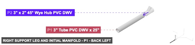
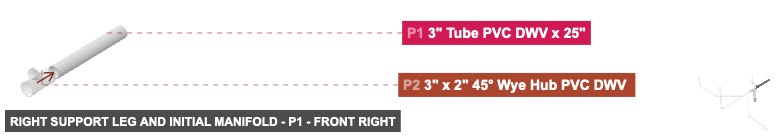
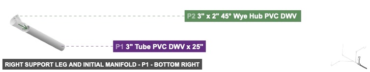
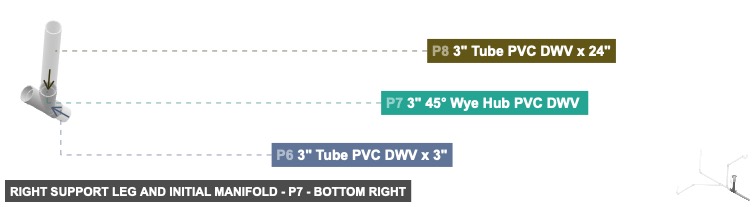
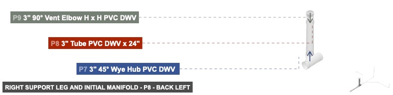
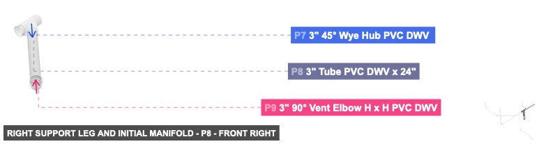
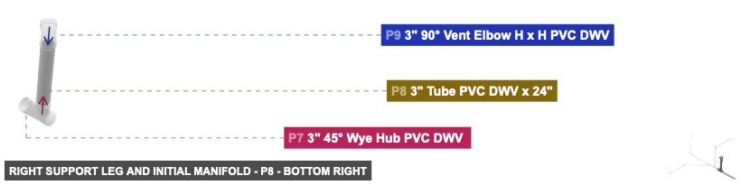
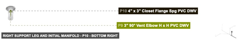
Group: Right Support Leg and Initial Manifold
Forms the main structural base on the right side and the initial section of the central distribution manifold.
1. Connect P1's 3 inch Male SLIP (facing front) to P2's 3 inch DWV Female (facing back). Ensure P1's other 3 inch Male SLIP faces back. 2. Connect P6's 3 inch Male SLIP (facing back) to P2's 3 inch DWV Female (facing front). 3. Connect P6's 3 inch Male SLIP (facing front) to P7's 3 inch DWV Female (facing back). 4. Connect P8's 3 inch Male SLIP (facing back-left) to P7's 3 inch DWV Female (facing front-right). 5. Connect P8's 3 inch Male SLIP (facing front-right) to P9's 3 inch DWV Female (facing back-left). 6. Connect P10's 3 inch DWV Male (facing bottom) to P9's 3 inch DWV Female (facing top).
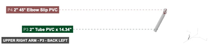
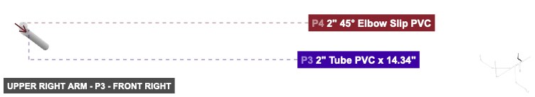
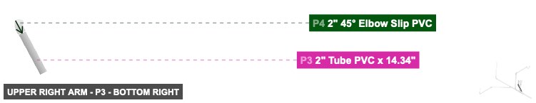
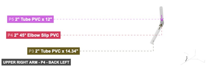
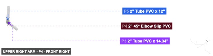
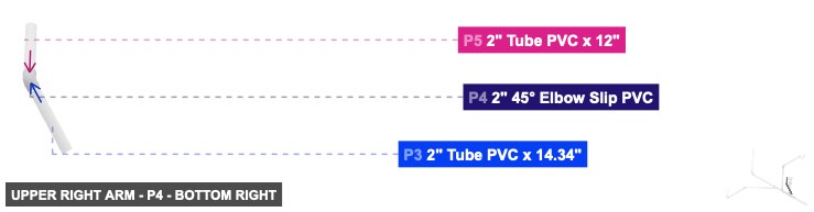
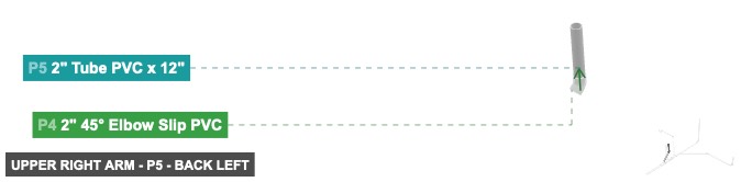
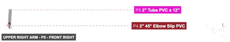
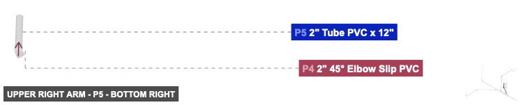
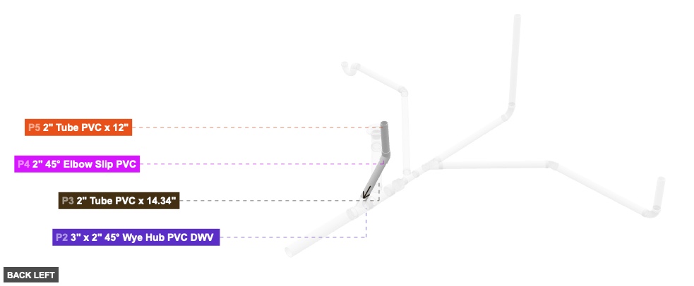
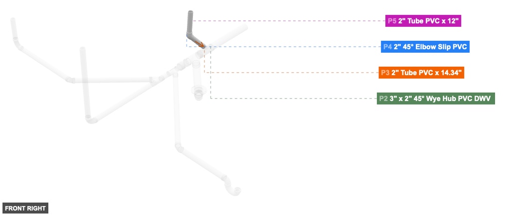
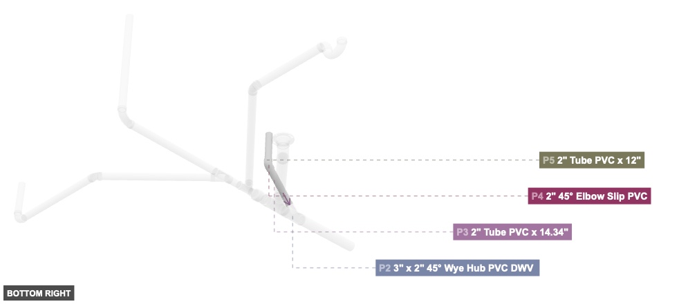
Group: Upper Right Arm
Creates an upward-extending arm from the initial manifold.
1. Connect P3's 2 inch Male SLIP (facing front-top) to P4's 2 inch Female SLIP (facing back-bottom). 2. Connect P5's 2 inch Male SLIP (facing bottom) to P4's 2 inch Female SLIP (facing top). Ensure P5's other 2 inch Male SLIP faces top.
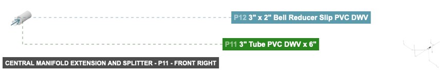
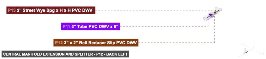
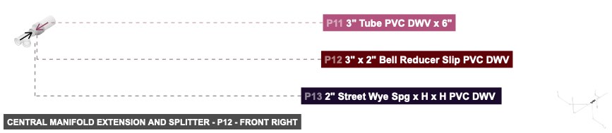
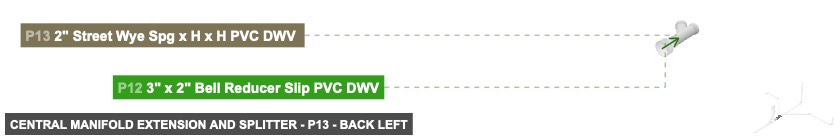
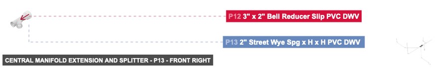
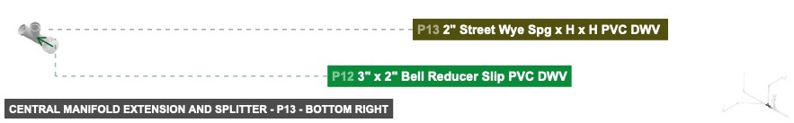
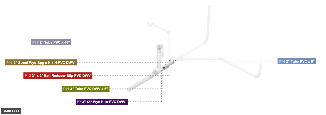
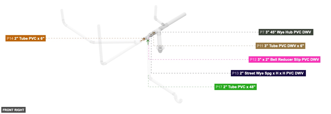
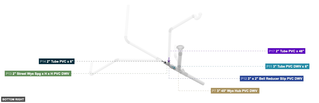
Group: Central Manifold Extension and Splitter
Extends the main manifold and creates a primary branching point for subsequent assemblies.
1. Connect P11's 3 inch Male SLIP (facing front) to P12's 3 inch Female SLIP (facing back). 2. Connect P13's 2 inch DWV Male (facing back) to P12's 2 inch Female SLIP (facing front).
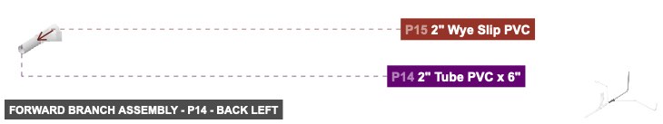
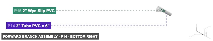
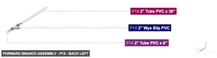
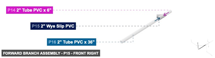
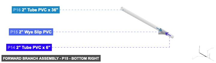
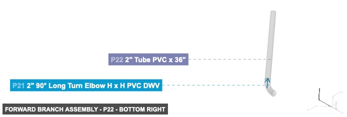
Group: Forward Branch Assembly
Forms a major branch extending forward from the central manifold, itself having a branching point.
1. Connect P14's 2 inch Male SLIP (facing front) to P15's 2 inch Female SLIP (facing back). 2. Connect P16's 2 inch Male SLIP (facing back) to P15's 2 inch Female SLIP (facing front). 3. Connect P16's 2 inch Male SLIP (facing front) to P21's 2 inch DWV Female (facing back). 4. Connect P22's 2 inch Male SLIP (facing bottom) to P21's 2 inch DWV Female (facing top). Ensure P22's other 2 inch Male SLIP faces top.
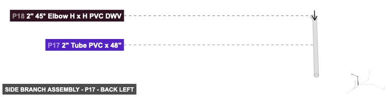
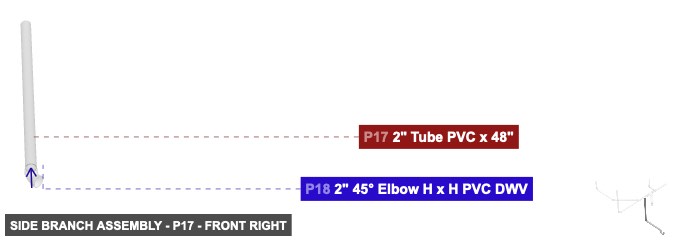
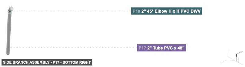
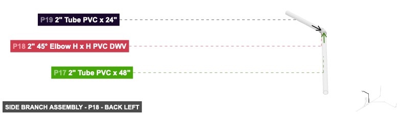
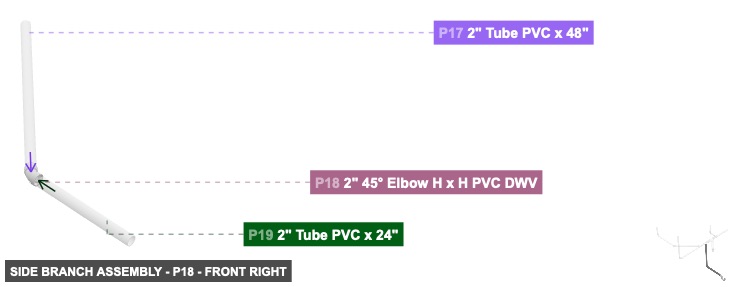
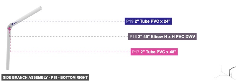
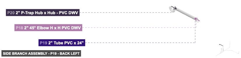
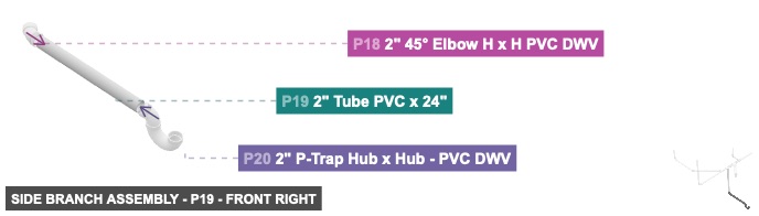
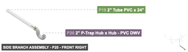
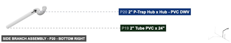
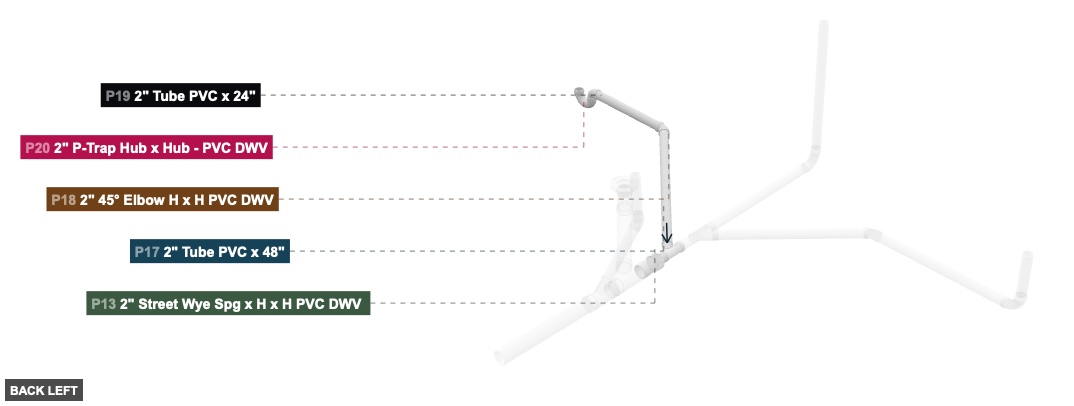
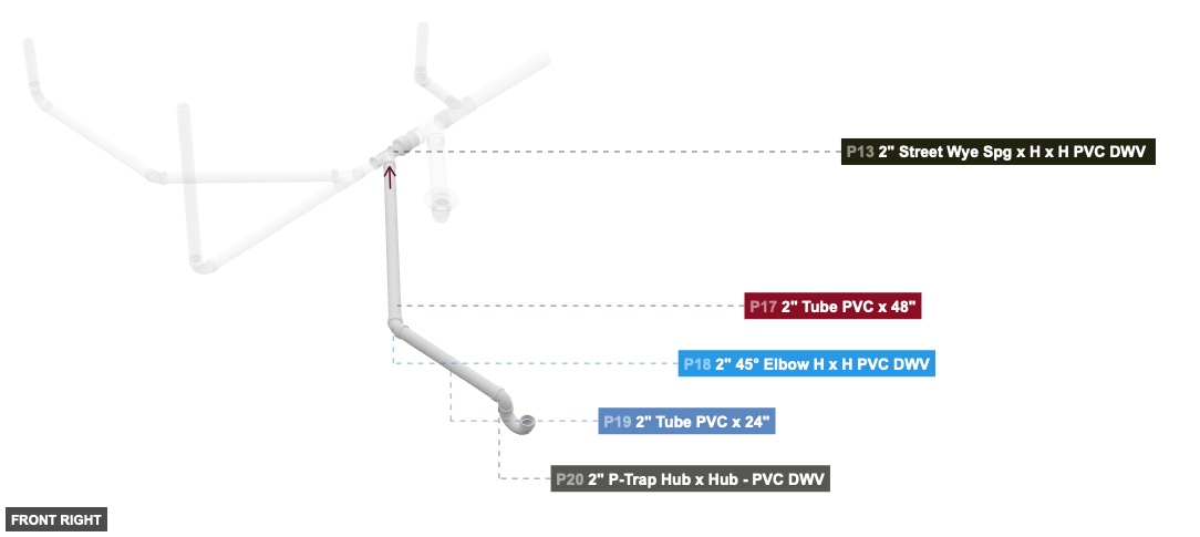
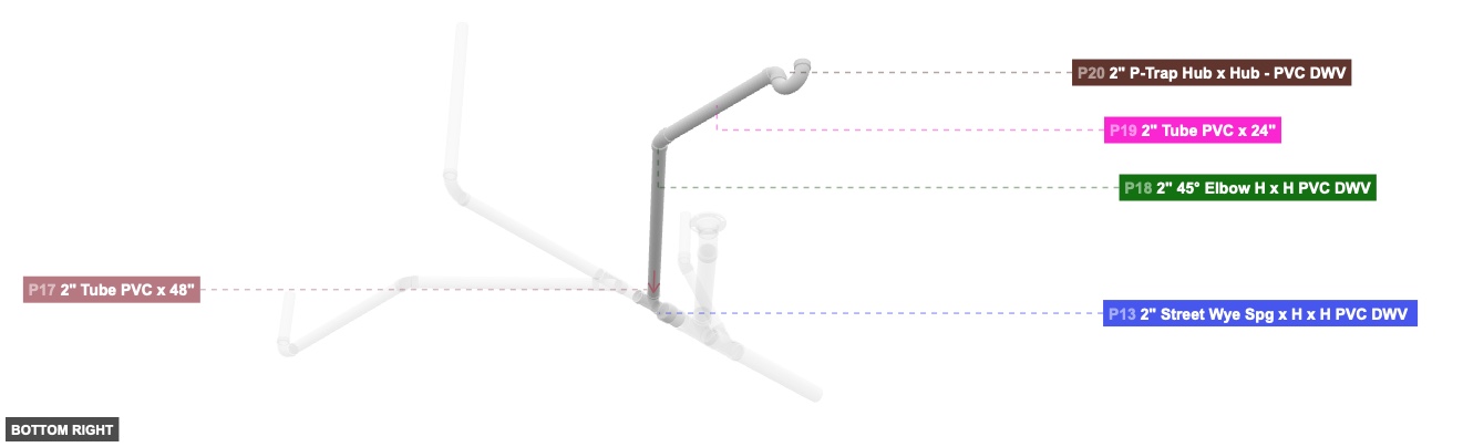
Group: Side Branch Assembly
Forms a major branch extending to the side from the central manifold.
1. Connect P17's 2 inch Male SLIP (facing front-right) to P18's 2 inch Female SLIP (facing back-left). 2. Connect P19's 2 inch Male SLIP (facing left) to P18's 2 inch Female SLIP (facing right). 3. Connect P20's 2 inch DWV Female (facing left) to P19's 2 inch Male SLIP (facing right). Ensure P20's other 2 inch DWV Female faces top.
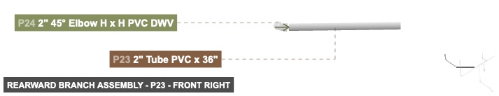
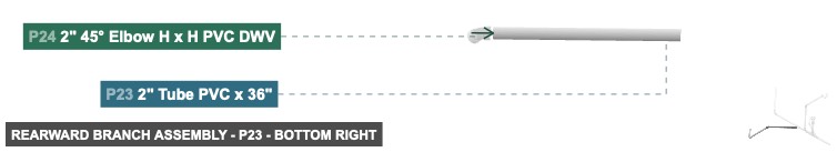
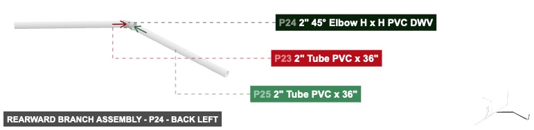
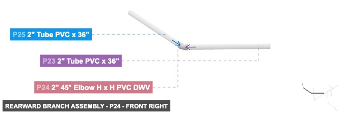
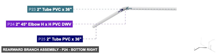
Group: Rearward Branch Assembly
Forms a branch extending rearward and to the side, originating from the 'Forward Branch Assembly'.
1. Connect P23's 2 inch Male SLIP (facing front-left) to P24's 2 inch Female SLIP (facing back-right). 2. Connect P25's 2 inch Male SLIP (facing right) to P24's 2 inch Female SLIP (facing left). 3. Connect P25's 2 inch Male SLIP (facing left) to P27's 2 inch DWV Female (facing right). 4. Connect P26's 2 inch Male SLIP (facing bottom) to P27's 2 inch DWV Female (facing top). Ensure P26's other 2 inch Male SLIP faces top.
Phase 3: Inter-Group Assembly
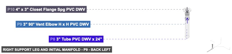
Attaching: Right Support Leg and Initial Manifold
Forms the main structural base on the right side and the initial section of the central distribution manifold.
This is the foundational group. Subsequent groups will attach to P2 and P7 of this assembly.
Angle: back left
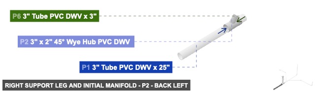
P1 (3" Tube PVC DWV 25" length) - attach its 3" M SLIP #1 facing front to part 2's 3" DWV F #2. Also, its 3" M SLIP #2 must be oriented back
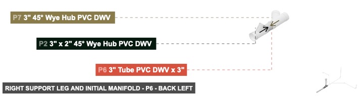
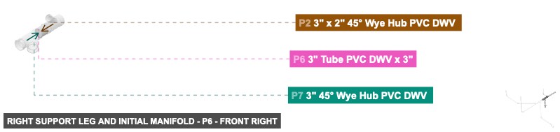
P2 (3" x 2" 45° Wye Hub PVC DWV ) - attach its 3" DWV F #1 facing front to part 6's 3" M SLIP #2, and its 3" DWV F #2, which is back-facing, should connect to part 1's 3" M SLIP #1, plus attach its 2" DWV F #1 facing front-top to part 3's 2" M SLIP #1
P6 (3" Tube PVC DWV 3" length) - connect its 3" M SLIP #1 oriented front links with part 7's 3" DWV F #3. After that, connect its 3" M SLIP #2 oriented back links with part 2's 3" DWV F #1
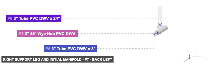
P7 (3" 45° Wye Hub PVC DWV ) - attach its 3" DWV F #1 facing front to part 11's 3" M SLIP #2. After that, attach its 3" DWV F #2 facing front-right to part 8's 3" M SLIP #2, then connect its 3" DWV F #3 oriented back links with part 6's 3" M SLIP #1
P8 (3" Tube PVC DWV 24" length) - its 3" M SLIP #1, which is front-right-facing, should connect to part 9's 3" DWV F #1. After that, its 3" M SLIP #2, which is back-left-facing, should connect to part 7's 3" DWV F #2
P9 (3" 90° Vent Elbow H x H PVC DWV) - connect its 3" DWV F #1 oriented back-left links with part 8's 3" M SLIP #1, also attach its 3" DWV F #2 facing top to part 10's 3" DWV M #1
P10 (4" x 3" Closet Flange Spg PVC DWV) - connect its 3" DWV M #1 oriented bottom links with part 9's 3" DWV F #2
3" Tube PVC DWV x 25"x 1 3" x 2" 45° Wye Hub PVC DWV x 1 3" Tube PVC DWV x 3"x 1 3" 45° Wye Hub PVC DWV x 1 3" Tube PVC DWV x 24"x 1 3" 90° Vent Elbow H x H PVC DWVx 1 4" x 3" Closet Flange Spg PVC DWVx 1
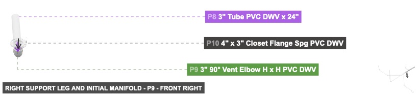
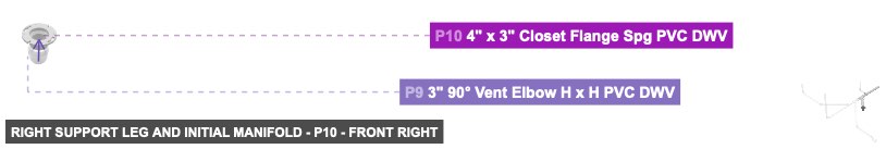
Angle: front right
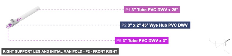
P1 (3" Tube PVC DWV 25" length) - attach its 3" M SLIP #1 facing front to part 2's 3" DWV F #2. Also, its 3" M SLIP #2 must be oriented back
P2 (3" x 2" 45° Wye Hub PVC DWV ) - attach its 3" DWV F #1 facing front to part 6's 3" M SLIP #2, and its 3" DWV F #2, which is back-facing, should connect to part 1's 3" M SLIP #1, plus attach its 2" DWV F #1 facing front-top to part 3's 2" M SLIP #1
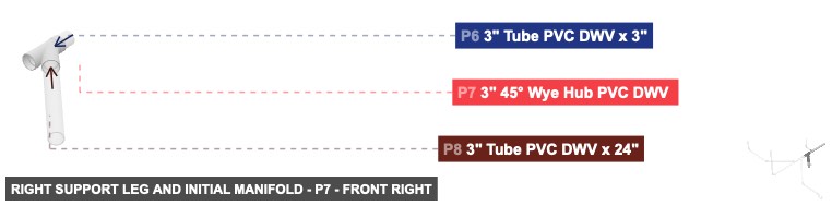
P6 (3" Tube PVC DWV 3" length) - connect its 3" M SLIP #1 oriented front links with part 7's 3" DWV F #3. After that, connect its 3" M SLIP #2 oriented back links with part 2's 3" DWV F #1
P7 (3" 45° Wye Hub PVC DWV ) - attach its 3" DWV F #1 facing front to part 11's 3" M SLIP #2. After that, attach its 3" DWV F #2 facing front-right to part 8's 3" M SLIP #2, then connect its 3" DWV F #3 oriented back links with part 6's 3" M SLIP #1
P8 (3" Tube PVC DWV 24" length) - its 3" M SLIP #1, which is front-right-facing, should connect to part 9's 3" DWV F #1. After that, its 3" M SLIP #2, which is back-left-facing, should connect to part 7's 3" DWV F #2
P9 (3" 90° Vent Elbow H x H PVC DWV) - connect its 3" DWV F #1 oriented back-left links with part 8's 3" M SLIP #1, also attach its 3" DWV F #2 facing top to part 10's 3" DWV M #1
P10 (4" x 3" Closet Flange Spg PVC DWV) - connect its 3" DWV M #1 oriented bottom links with part 9's 3" DWV F #2
3" Tube PVC DWV x 25"x 1 3" x 2" 45° Wye Hub PVC DWV x 1 3" Tube PVC DWV x 3"x 1 3" 45° Wye Hub PVC DWV x 1 3" Tube PVC DWV x 24"x 1 3" 90° Vent Elbow H x H PVC DWVx 1 4" x 3" Closet Flange Spg PVC DWVx 1
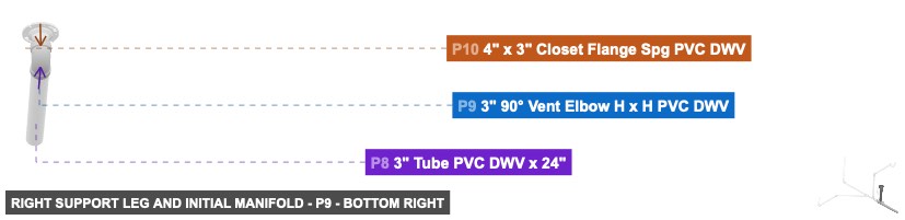
Angle: bottom right
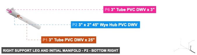
P1 (3" Tube PVC DWV 25" length) - attach its 3" M SLIP #1 facing front to part 2's 3" DWV F #2. Also, its 3" M SLIP #2 must be oriented back
P2 (3" x 2" 45° Wye Hub PVC DWV ) - attach its 3" DWV F #1 facing front to part 6's 3" M SLIP #2, and its 3" DWV F #2, which is back-facing, should connect to part 1's 3" M SLIP #1, plus attach its 2" DWV F #1 facing front-top to part 3's 2" M SLIP #1
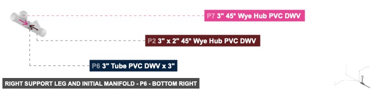
P6 (3" Tube PVC DWV 3" length) - connect its 3" M SLIP #1 oriented front links with part 7's 3" DWV F #3. After that, connect its 3" M SLIP #2 oriented back links with part 2's 3" DWV F #1
P7 (3" 45° Wye Hub PVC DWV ) - attach its 3" DWV F #1 facing front to part 11's 3" M SLIP #2. After that, attach its 3" DWV F #2 facing front-right to part 8's 3" M SLIP #2, then connect its 3" DWV F #3 oriented back links with part 6's 3" M SLIP #1
P8 (3" Tube PVC DWV 24" length) - its 3" M SLIP #1, which is front-right-facing, should connect to part 9's 3" DWV F #1. After that, its 3" M SLIP #2, which is back-left-facing, should connect to part 7's 3" DWV F #2
P9 (3" 90° Vent Elbow H x H PVC DWV) - connect its 3" DWV F #1 oriented back-left links with part 8's 3" M SLIP #1, also attach its 3" DWV F #2 facing top to part 10's 3" DWV M #1
P10 (4" x 3" Closet Flange Spg PVC DWV) - connect its 3" DWV M #1 oriented bottom links with part 9's 3" DWV F #2
3" Tube PVC DWV x 25"x 1 3" x 2" 45° Wye Hub PVC DWV x 1 3" Tube PVC DWV x 3"x 1 3" 45° Wye Hub PVC DWV x 1 3" Tube PVC DWV x 24"x 1 3" 90° Vent Elbow H x H PVC DWVx 1 4" x 3" Closet Flange Spg PVC DWVx 1 Attaching: Upper Right Arm
Creates an upward-extending arm from the initial manifold.
Attach this completed arm by connecting P3's 2 inch Male SLIP (facing back-bottom) to P2's 2 inch DWV Female (facing front-top) on the 'Right Support Leg and Initial Manifold' group.
Attaching: Central Manifold Extension and Splitter
Extends the main manifold and creates a primary branching point for subsequent assemblies.
Attach this assembly by connecting P11's 3 inch Male SLIP (facing back) to P7's 3 inch DWV Female (facing front) on the 'Right Support Leg and Initial Manifold' group.
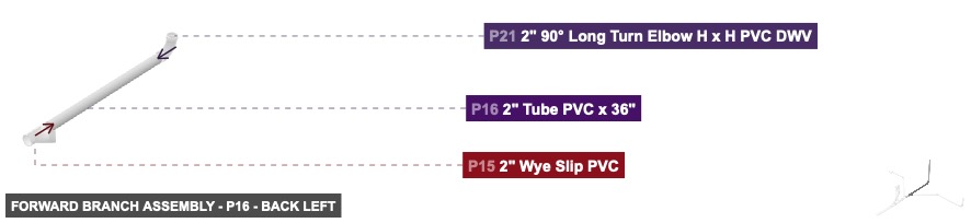
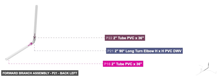
Attaching: Forward Branch Assembly
Forms a major branch extending forward from the central manifold, itself having a branching point.
Attach this assembly by connecting P14's 2 inch Male SLIP (facing back) to P13's 2 inch DWV Female (facing front) on the 'Central Manifold Extension and Splitter' group.
Angle: back left
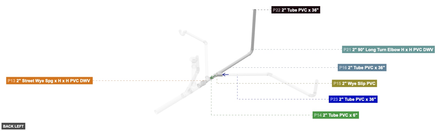
P14 (2" Tube PVC 6" length) - attach its 2" M SLIP #1 facing front to part 15's 2" F SLIP #2, and attach its 2" M SLIP #2 facing back to part 13's 2" DWV F #1
P15 (2" Wye Slip PVC) - attach its 2" F SLIP #1 facing front to part 16's 2" M SLIP #2, plus its 2" F SLIP #2, which is back-facing, should connect to part 14's 2" M SLIP #1. Also, attach its 2" F SLIP #3 facing front-left to part 23's 2" M SLIP #2
P16 (2" Tube PVC 36" length) - connect its 2" M SLIP #1 oriented front links with part 21's 2" DWV F #1. Additionally, its 2" M SLIP #2, which is back-facing, should connect to part 15's 2" F SLIP #1
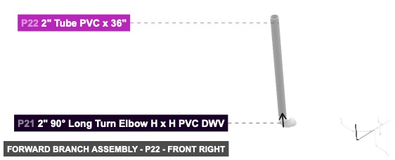
P21 (2" 90° Long Turn Elbow H x H PVC DWV) - connect its 2" DWV F #1 oriented back links with part 16's 2" M SLIP #1. Additionally, attach its 2" DWV F #2 facing top to part 22's 2" M SLIP #2
P22 (2" Tube PVC 36" length) - its 2" M SLIP #2, which is bottom-facing, should connect to part 21's 2" DWV F #2, also its 2" M SLIP #1 must be oriented top
2" Tube PVC x 6"x 1 2" Wye Slip PVCx 1 2" Tube PVC x 36"x 2 2" 90° Long Turn Elbow H x H PVC DWVx 1
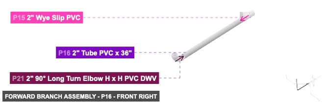
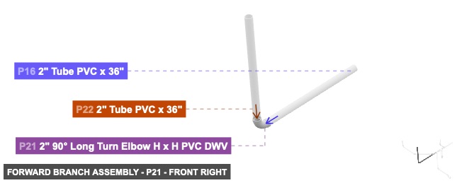
Angle: front right
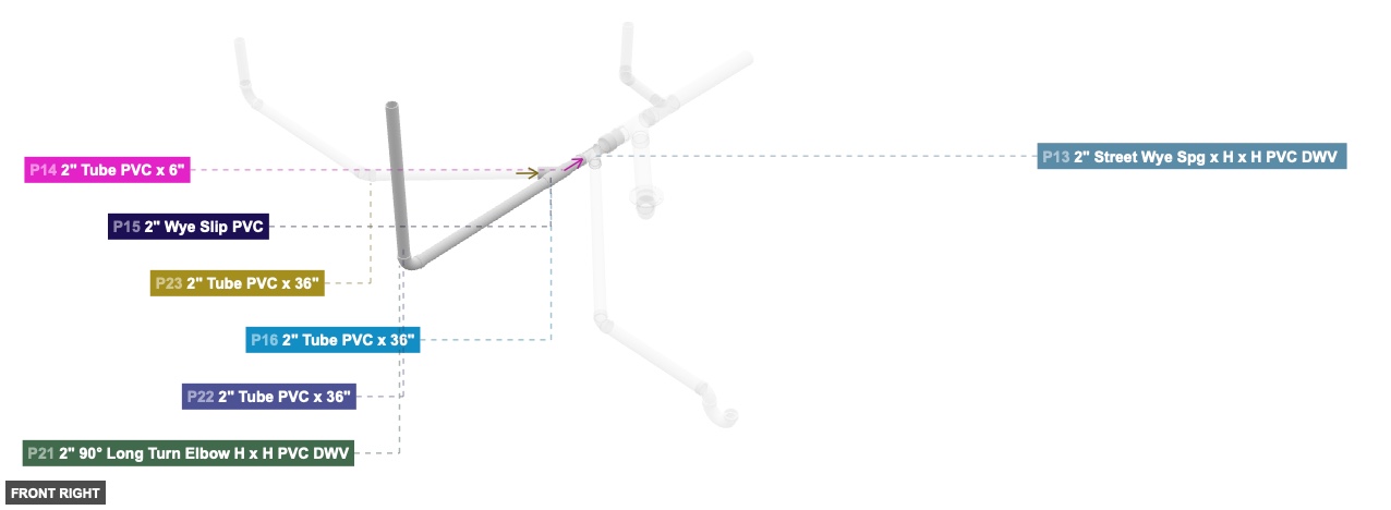
P14 (2" Tube PVC 6" length) - attach its 2" M SLIP #1 facing front to part 15's 2" F SLIP #2, and attach its 2" M SLIP #2 facing back to part 13's 2" DWV F #1
P15 (2" Wye Slip PVC) - attach its 2" F SLIP #1 facing front to part 16's 2" M SLIP #2, plus its 2" F SLIP #2, which is back-facing, should connect to part 14's 2" M SLIP #1. Also, attach its 2" F SLIP #3 facing front-left to part 23's 2" M SLIP #2
P16 (2" Tube PVC 36" length) - connect its 2" M SLIP #1 oriented front links with part 21's 2" DWV F #1. Additionally, its 2" M SLIP #2, which is back-facing, should connect to part 15's 2" F SLIP #1
P21 (2" 90° Long Turn Elbow H x H PVC DWV) - connect its 2" DWV F #1 oriented back links with part 16's 2" M SLIP #1. Additionally, attach its 2" DWV F #2 facing top to part 22's 2" M SLIP #2
P22 (2" Tube PVC 36" length) - its 2" M SLIP #2, which is bottom-facing, should connect to part 21's 2" DWV F #2, also its 2" M SLIP #1 must be oriented top
2" Tube PVC x 6"x 1 2" Wye Slip PVCx 1 2" Tube PVC x 36"x 2 2" 90° Long Turn Elbow H x H PVC DWVx 1
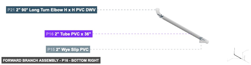
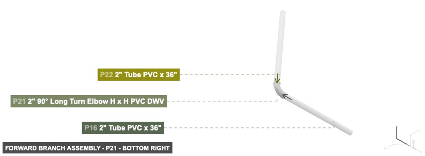
Angle: bottom right
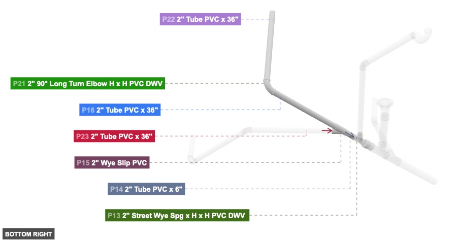
P14 (2" Tube PVC 6" length) - attach its 2" M SLIP #1 facing front to part 15's 2" F SLIP #2, and attach its 2" M SLIP #2 facing back to part 13's 2" DWV F #1
P15 (2" Wye Slip PVC) - attach its 2" F SLIP #1 facing front to part 16's 2" M SLIP #2, plus its 2" F SLIP #2, which is back-facing, should connect to part 14's 2" M SLIP #1. Also, attach its 2" F SLIP #3 facing front-left to part 23's 2" M SLIP #2
P16 (2" Tube PVC 36" length) - connect its 2" M SLIP #1 oriented front links with part 21's 2" DWV F #1. Additionally, its 2" M SLIP #2, which is back-facing, should connect to part 15's 2" F SLIP #1
P21 (2" 90° Long Turn Elbow H x H PVC DWV) - connect its 2" DWV F #1 oriented back links with part 16's 2" M SLIP #1. Additionally, attach its 2" DWV F #2 facing top to part 22's 2" M SLIP #2
P22 (2" Tube PVC 36" length) - its 2" M SLIP #2, which is bottom-facing, should connect to part 21's 2" DWV F #2, also its 2" M SLIP #1 must be oriented top
2" Tube PVC x 6"x 1 2" Wye Slip PVCx 1 2" Tube PVC x 36"x 2 2" 90° Long Turn Elbow H x H PVC DWVx 1 Attaching: Side Branch Assembly
Forms a major branch extending to the side from the central manifold.
Attach this assembly by connecting P17's 2 inch Male SLIP (facing back-left) to P13's 2 inch DWV Female (facing front-right) on the 'Central Manifold Extension and Splitter' group.
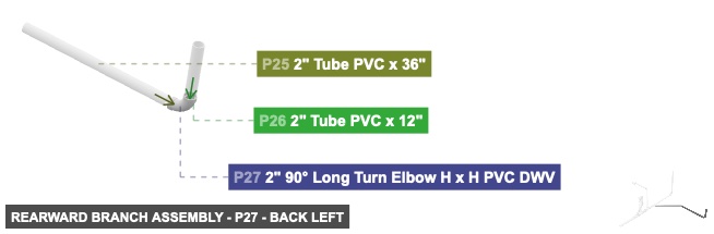
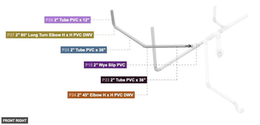
Attaching: Rearward Branch Assembly
Forms a branch extending rearward and to the side, originating from the 'Forward Branch Assembly'.
Attach this assembly by connecting P23's 2 inch Male SLIP (facing back-right) to P15's 2 inch Female SLIP (facing front-left) on the 'Forward Branch Assembly' group.
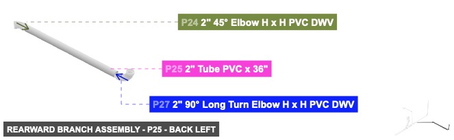
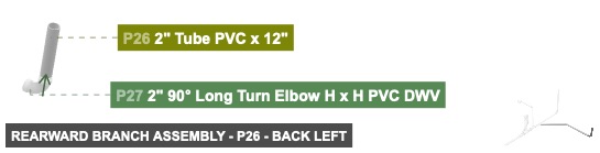
Angle: back left
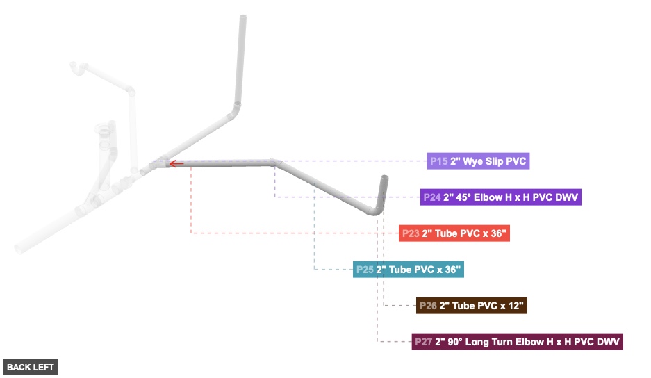
P23 (2" Tube PVC 36" length) - its 2" M SLIP #1, which is front-left-facing, should connect to part 24's 2" F SLIP #1. After that, its 2" M SLIP #2, which is back-right-facing, should connect to part 15's 2" F SLIP #3
P24 (2" 45° Elbow H x H PVC DWV) - connect its 2" F SLIP #1 oriented back-right links with part 23's 2" M SLIP #1, plus its 2" F SLIP #2, which is left-facing, should connect to part 25's 2" M SLIP #2
P25 (2" Tube PVC 36" length) - attach its 2" M SLIP #1 facing left to part 27's 2" DWV F #1. After that, connect its 2" M SLIP #2 oriented right links with part 24's 2" F SLIP #2
P26 (2" Tube PVC 12" length) - connect its 2" M SLIP #2 oriented bottom links with part 27's 2" DWV F #2. After that, its 2" M SLIP #1 needs to point top
P27 (2" 90° Long Turn Elbow H x H PVC DWV) - its 2" DWV F #1, which is right-facing, should connect to part 25's 2" M SLIP #1, plus attach its 2" DWV F #2 facing top to part 26's 2" M SLIP #2
2" Tube PVC x 36"x 2 2" 45° Elbow H x H PVC DWVx 1 2" Tube PVC x 12"x 1 2" 90° Long Turn Elbow H x H PVC DWVx 1
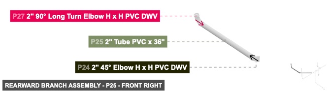
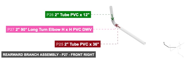
Angle: front right
P23 (2" Tube PVC 36" length) - its 2" M SLIP #1, which is front-left-facing, should connect to part 24's 2" F SLIP #1. After that, its 2" M SLIP #2, which is back-right-facing, should connect to part 15's 2" F SLIP #3
P24 (2" 45° Elbow H x H PVC DWV) - connect its 2" F SLIP #1 oriented back-right links with part 23's 2" M SLIP #1, plus its 2" F SLIP #2, which is left-facing, should connect to part 25's 2" M SLIP #2
P25 (2" Tube PVC 36" length) - attach its 2" M SLIP #1 facing left to part 27's 2" DWV F #1. After that, connect its 2" M SLIP #2 oriented right links with part 24's 2" F SLIP #2
P26 (2" Tube PVC 12" length) - connect its 2" M SLIP #2 oriented bottom links with part 27's 2" DWV F #2. After that, its 2" M SLIP #1 needs to point top
P27 (2" 90° Long Turn Elbow H x H PVC DWV) - its 2" DWV F #1, which is right-facing, should connect to part 25's 2" M SLIP #1, plus attach its 2" DWV F #2 facing top to part 26's 2" M SLIP #2
2" Tube PVC x 36"x 2 2" 45° Elbow H x H PVC DWVx 1 2" Tube PVC x 12"x 1 2" 90° Long Turn Elbow H x H PVC DWVx 1
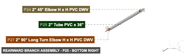
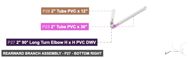
Angle: bottom right
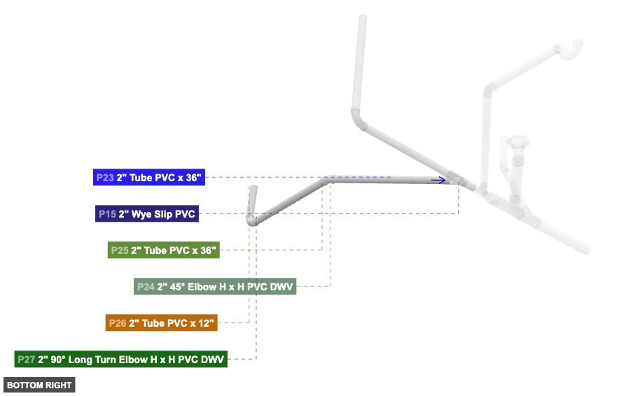
P23 (2" Tube PVC 36" length) - its 2" M SLIP #1, which is front-left-facing, should connect to part 24's 2" F SLIP #1. After that, its 2" M SLIP #2, which is back-right-facing, should connect to part 15's 2" F SLIP #3
P24 (2" 45° Elbow H x H PVC DWV) - connect its 2" F SLIP #1 oriented back-right links with part 23's 2" M SLIP #1, plus its 2" F SLIP #2, which is left-facing, should connect to part 25's 2" M SLIP #2
P25 (2" Tube PVC 36" length) - attach its 2" M SLIP #1 facing left to part 27's 2" DWV F #1. After that, connect its 2" M SLIP #2 oriented right links with part 24's 2" F SLIP #2
P26 (2" Tube PVC 12" length) - connect its 2" M SLIP #2 oriented bottom links with part 27's 2" DWV F #2. After that, its 2" M SLIP #1 needs to point top
P27 (2" 90° Long Turn Elbow H x H PVC DWV) - its 2" DWV F #1, which is right-facing, should connect to part 25's 2" M SLIP #1, plus attach its 2" DWV F #2 facing top to part 26's 2" M SLIP #2
2" Tube PVC x 36"x 2 2" 45° Elbow H x H PVC DWVx 1 2" Tube PVC x 12"x 1 2" 90° Long Turn Elbow H x H PVC DWVx 1