Pump Design - Comprehensive Assembly Plan And Visual Guide
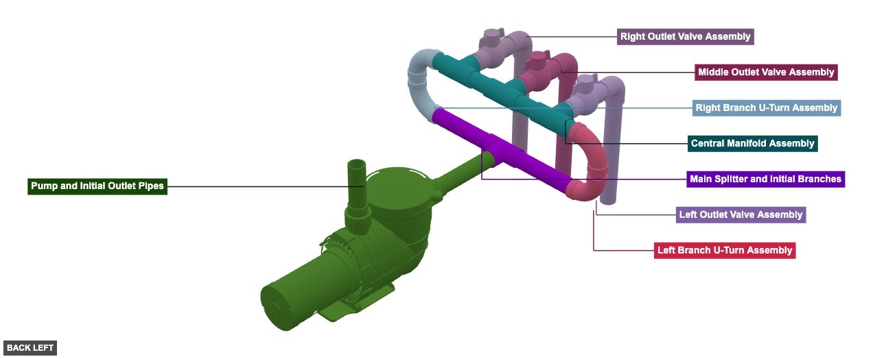
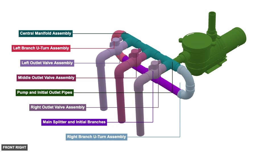
A system consisting of a central pump (P1) that feeds water into a piping network. The flow is split (P4) into two branches, which then route upwards and connect to a central distribution manifold (composed of P13, P15, P18 and connecting pipes). This manifold has three outlets, each equipped with a ball valve (P21, P26, P31) and leading to a long vertical pipe (P24, P29, P34). - Pool/Spa Pump and Piping System
Phase 1: Group Overview
Angle: back left

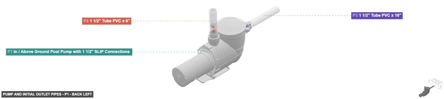
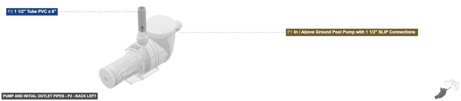
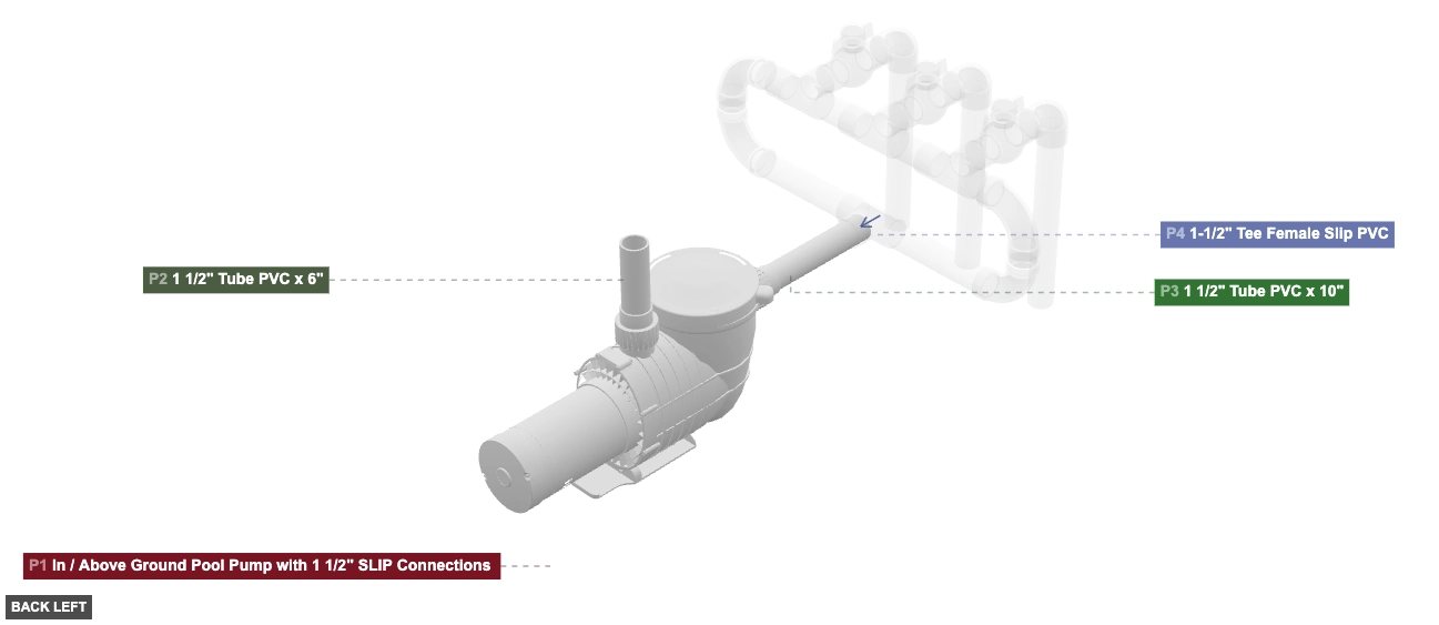
Pump and Initial Outlet Pipes
 In / Above Ground Pool Pump with 1 1/2" SLIP Connections x 1
 1 1/2" Tube PVC x 6"x 1
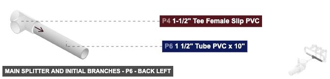
1 1/2" Tube PVC x 10"x 1 Main Splitter and Initial Branches
 1-1/2" Tee Female Slip PVCx 1
1 1/2" Tube PVC x 10"x 2 Left Branch U-Turn Assembly
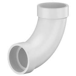 1-1/2" 90° Long Turn Elbow H x H PVC DWVx 2
1 1/2" Tube PVC x 2"x 1 Right Branch U-Turn Assembly
1-1/2" 90° Long Turn Elbow H x H PVC DWVx 2 1 1/2" Tube PVC x 2"x 1 Central Manifold Assembly
1-1/2" Tee Female Slip PVCx 3 1 1/2" Tube PVC x 3"x 2 1 1/2" Tube PVC x 5"x 2 Left Outlet Valve Assembly
1 1/2" Tube PVC x 3"x 2 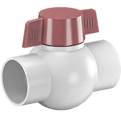 1-1/2" Ball Valve Slip PVCx 1
 1-1/2" 90° Elbow Slip PVC x 1
1 1/2" Tube PVC x 15"x 1 Middle Outlet Valve Assembly
1 1/2" Tube PVC x 3"x 2 1-1/2" Ball Valve Slip PVCx 1 1-1/2" 90° Elbow Slip PVC x 1 1 1/2" Tube PVC x 15"x 1 Right Outlet Valve Assembly
1 1/2" Tube PVC x 3"x 2 1-1/2" Ball Valve Slip PVCx 1 1-1/2" 90° Elbow Slip PVC x 1 1 1/2" Tube PVC x 15"x 1
Angle: front right
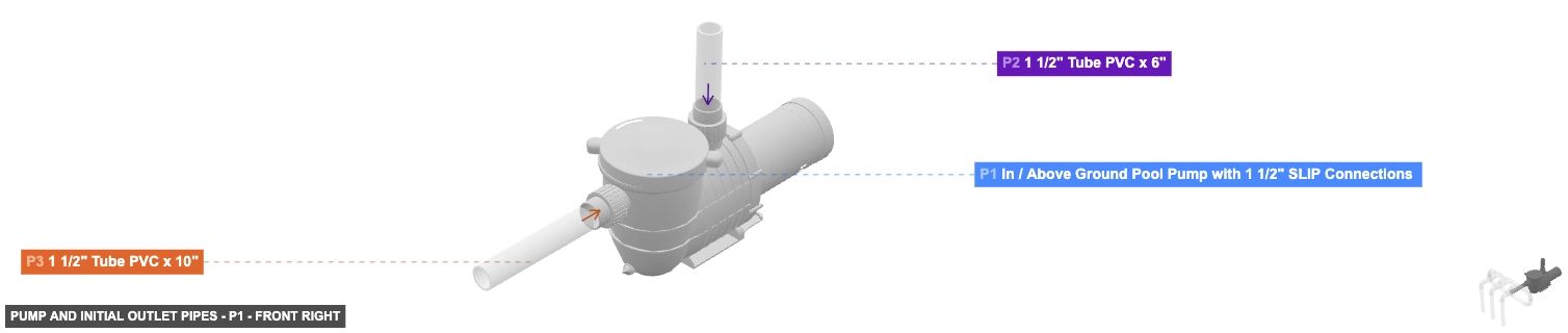
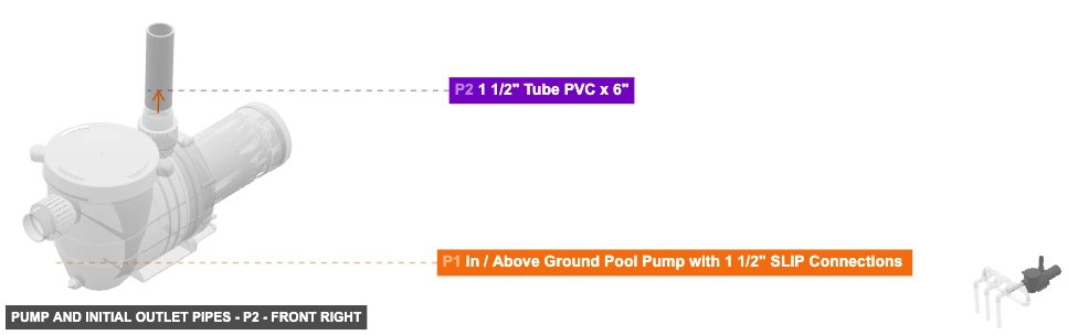
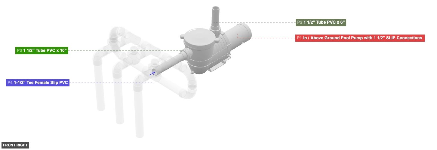
Pump and Initial Outlet Pipes
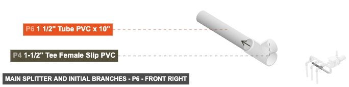
In / Above Ground Pool Pump with 1 1/2" SLIP Connections x 1 1 1/2" Tube PVC x 6"x 1 1 1/2" Tube PVC x 10"x 1 Main Splitter and Initial Branches
1-1/2" Tee Female Slip PVCx 1 1 1/2" Tube PVC x 10"x 2 Left Branch U-Turn Assembly
1-1/2" 90° Long Turn Elbow H x H PVC DWVx 2 1 1/2" Tube PVC x 2"x 1 Right Branch U-Turn Assembly
1-1/2" 90° Long Turn Elbow H x H PVC DWVx 2 1 1/2" Tube PVC x 2"x 1 Central Manifold Assembly
1-1/2" Tee Female Slip PVCx 3 1 1/2" Tube PVC x 3"x 2 1 1/2" Tube PVC x 5"x 2 Left Outlet Valve Assembly
1 1/2" Tube PVC x 3"x 2 1-1/2" Ball Valve Slip PVCx 1 1-1/2" 90° Elbow Slip PVC x 1 1 1/2" Tube PVC x 15"x 1 Middle Outlet Valve Assembly
1 1/2" Tube PVC x 3"x 2 1-1/2" Ball Valve Slip PVCx 1 1-1/2" 90° Elbow Slip PVC x 1 1 1/2" Tube PVC x 15"x 1 Right Outlet Valve Assembly
1 1/2" Tube PVC x 3"x 2 1-1/2" Ball Valve Slip PVCx 1 1-1/2" 90° Elbow Slip PVC x 1 1 1/2" Tube PVC x 15"x 1
Angle: bottom right
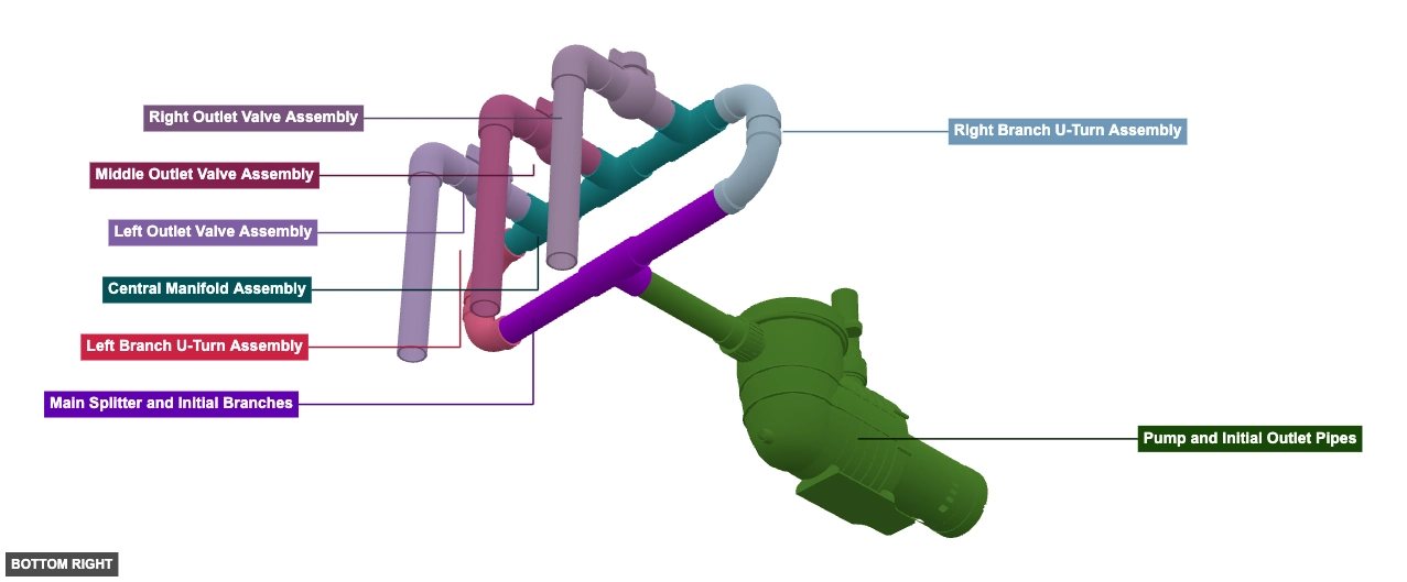
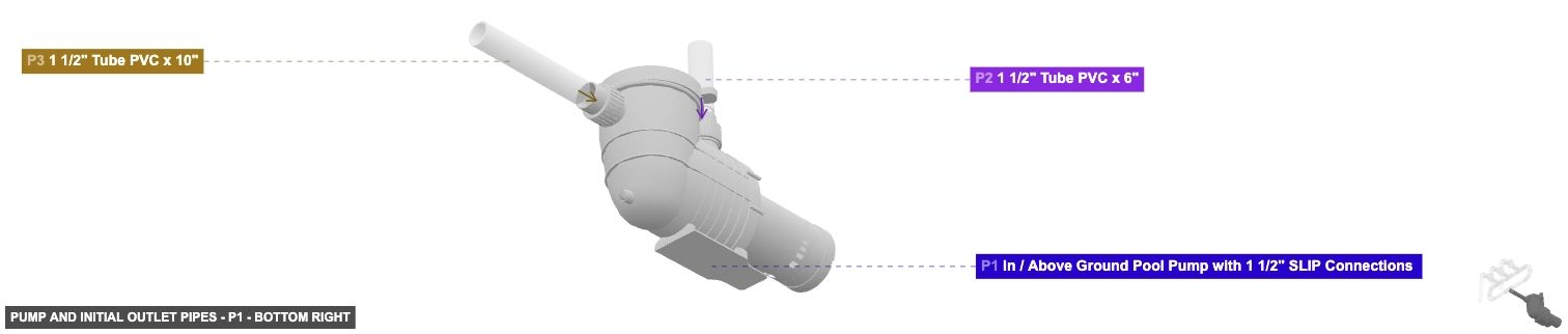
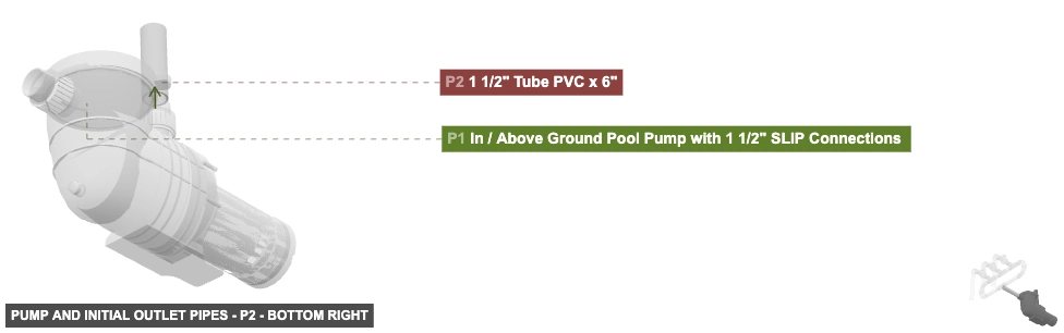
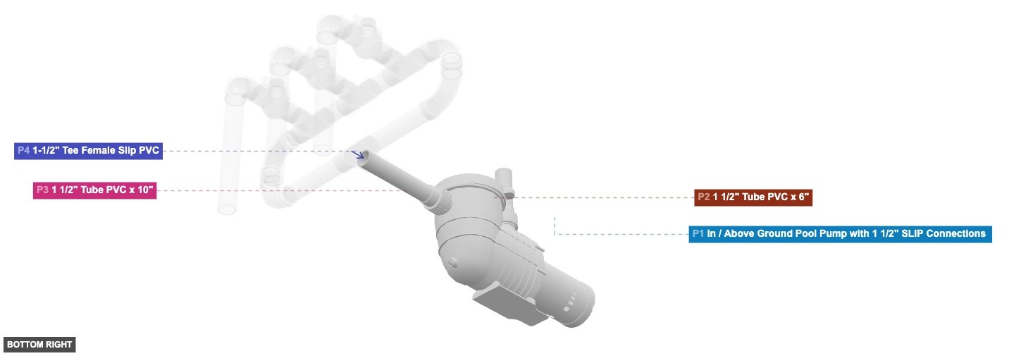
Pump and Initial Outlet Pipes
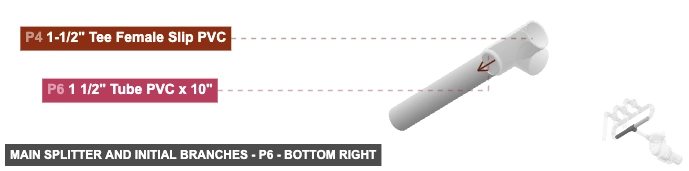
In / Above Ground Pool Pump with 1 1/2" SLIP Connections x 1 1 1/2" Tube PVC x 6"x 1 1 1/2" Tube PVC x 10"x 1 Main Splitter and Initial Branches
1-1/2" Tee Female Slip PVCx 1 1 1/2" Tube PVC x 10"x 2 Left Branch U-Turn Assembly
1-1/2" 90° Long Turn Elbow H x H PVC DWVx 2 1 1/2" Tube PVC x 2"x 1 Right Branch U-Turn Assembly
1-1/2" 90° Long Turn Elbow H x H PVC DWVx 2 1 1/2" Tube PVC x 2"x 1 Central Manifold Assembly
1-1/2" Tee Female Slip PVCx 3 1 1/2" Tube PVC x 3"x 2 1 1/2" Tube PVC x 5"x 2 Left Outlet Valve Assembly
1 1/2" Tube PVC x 3"x 2 1-1/2" Ball Valve Slip PVCx 1 1-1/2" 90° Elbow Slip PVC x 1 1 1/2" Tube PVC x 15"x 1 Middle Outlet Valve Assembly
1 1/2" Tube PVC x 3"x 2 1-1/2" Ball Valve Slip PVCx 1 1-1/2" 90° Elbow Slip PVC x 1 1 1/2" Tube PVC x 15"x 1 Right Outlet Valve Assembly
1 1/2" Tube PVC x 3"x 2 1-1/2" Ball Valve Slip PVCx 1 1-1/2" 90° Elbow Slip PVC x 1 1 1/2" Tube PVC x 15"x 1 Phase 2: Individual Group Assembly
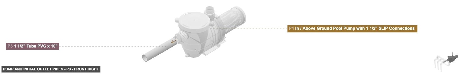
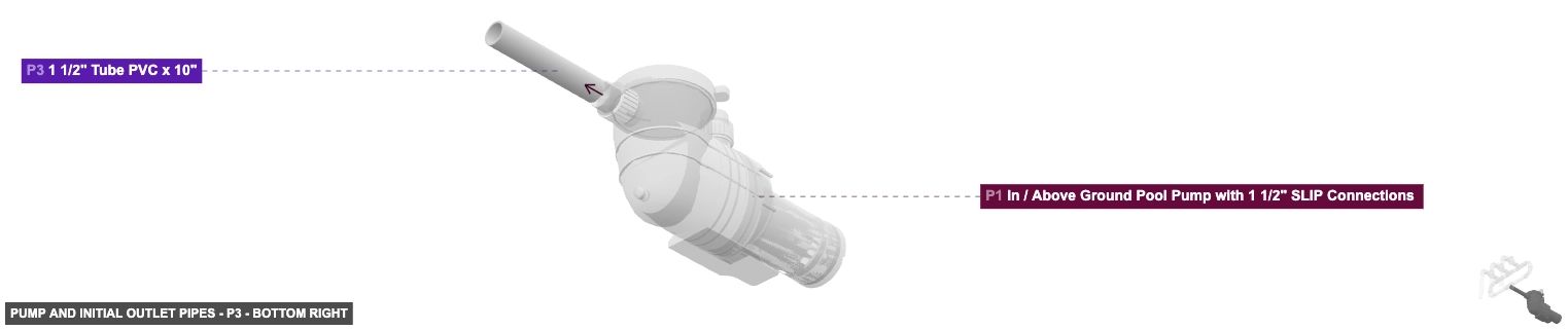
Group: Pump and Initial Outlet Pipes
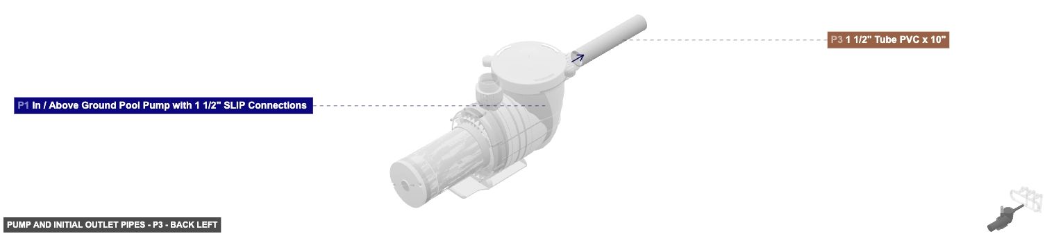
To assemble the main pump and its immediate outlet pipes.
Connect P2's 1.5 inch Male SLIP (bottom end) to P1's (Pump) 1.5 inch Female SLIP (top port). Connect P3's 1.5 inch Male SLIP (back end) to P1's (Pump) 1.5 inch Female SLIP (front port). P2's top 1.5 inch Male SLIP end will remain open or serve as an auxiliary port.
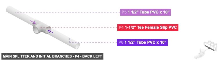
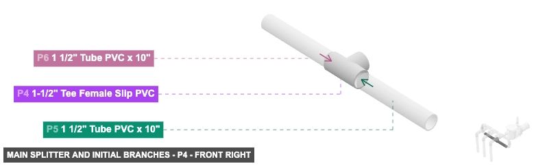
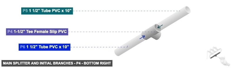
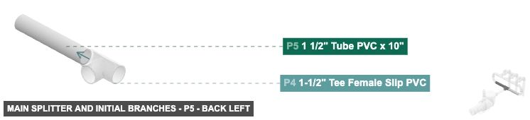
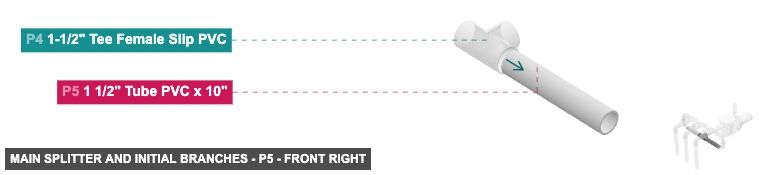
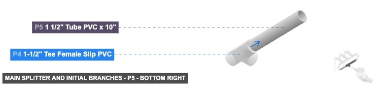
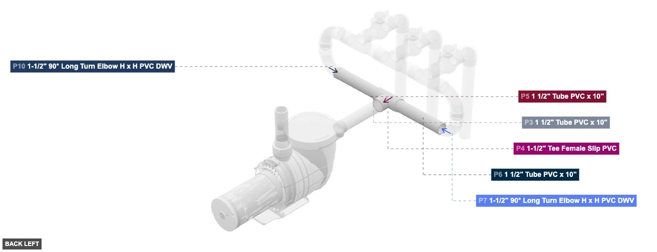
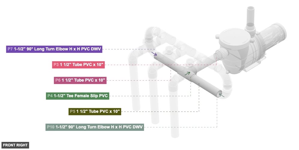
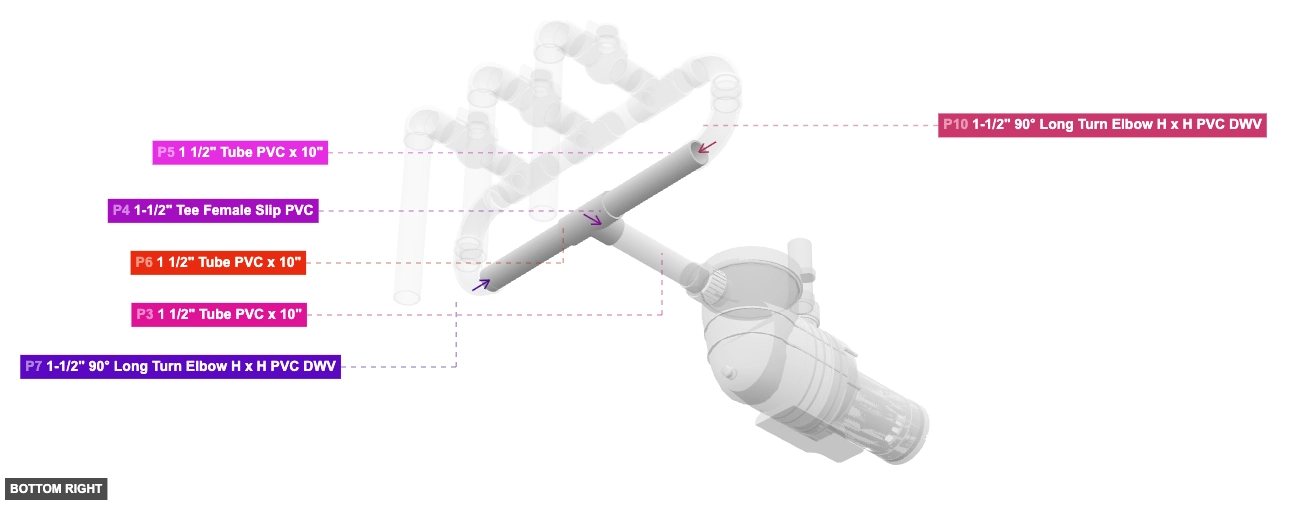
Group: Main Splitter and Initial Branches
To create the first split in the water flow and establish two main branches.
Connect P5's 1.5 inch Male SLIP (left end) to P4's (Tee) 1.5 inch Female SLIP (right port). Connect P6's 1.5 inch Male SLIP (right end) to P4's (Tee) 1.5 inch Female SLIP (left port).
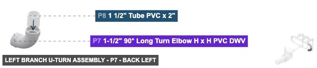
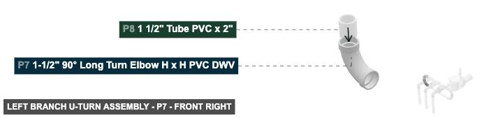
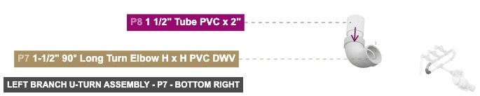
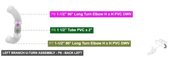
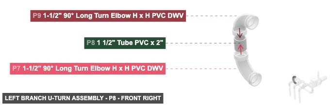
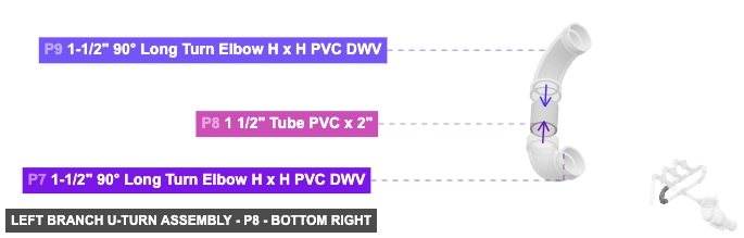
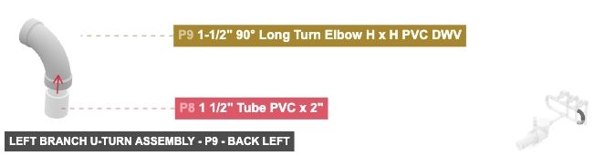
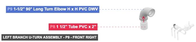
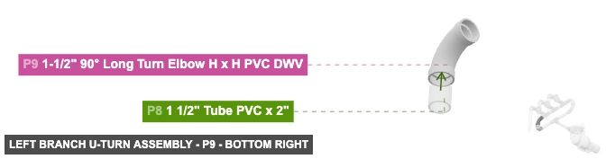
Group: Left Branch U-Turn Assembly
To redirect the flow from the left branch upwards and towards the central manifold.
Connect P8's 1.5 inch Male SLIP (bottom end) to P7's (90° Elbow) 1.5 inch Female DWV (top port). Connect P8's 1.5 inch Male SLIP (top end) to P9's (90° Elbow) 1.5 inch Female DWV (bottom port).
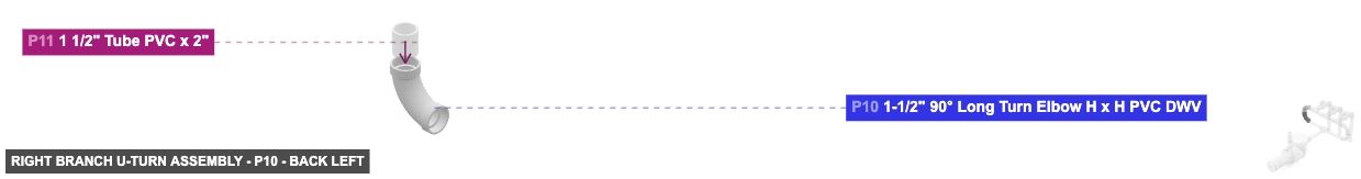
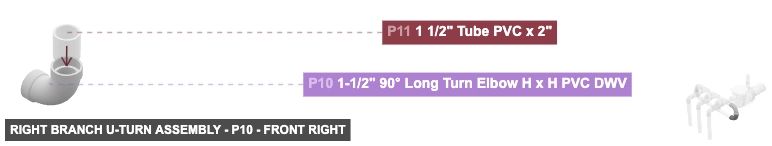
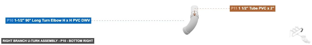
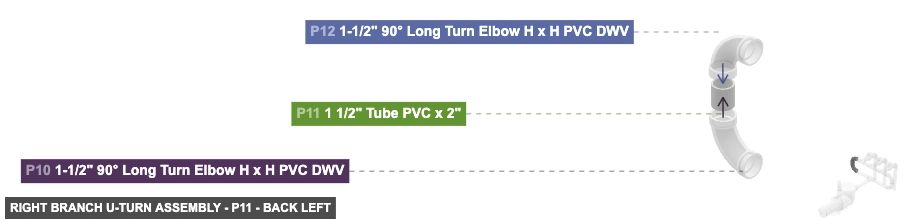
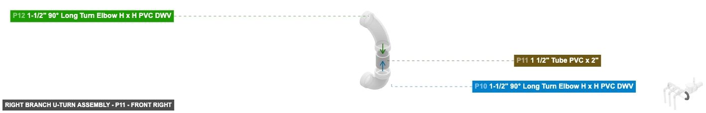
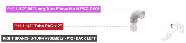
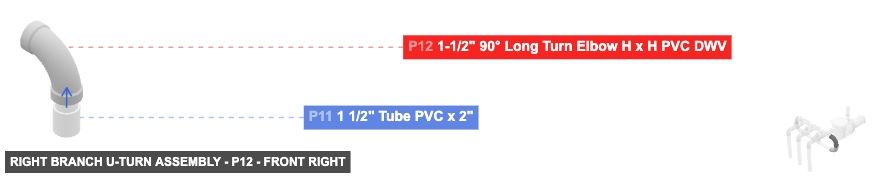
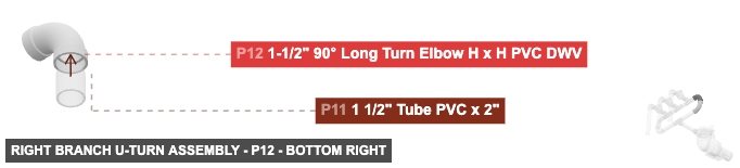
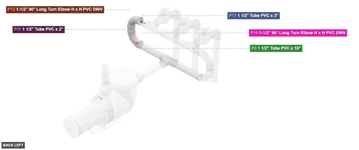
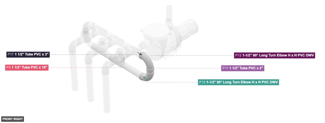
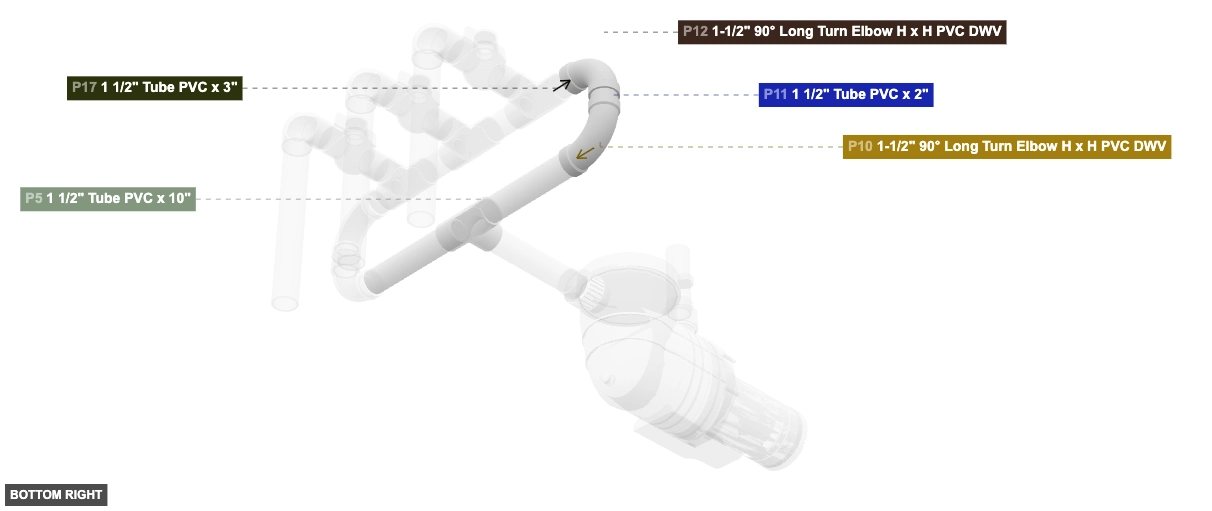
Group: Right Branch U-Turn Assembly
To redirect the flow from the right branch upwards and towards the central manifold.
Connect P11's 1.5 inch Male SLIP (bottom end) to P10's (90° Elbow) 1.5 inch Female DWV (top port). Connect P11's 1.5 inch Male SLIP (top end) to P12's (90° Elbow) 1.5 inch Female DWV (bottom port).
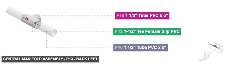
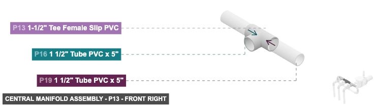
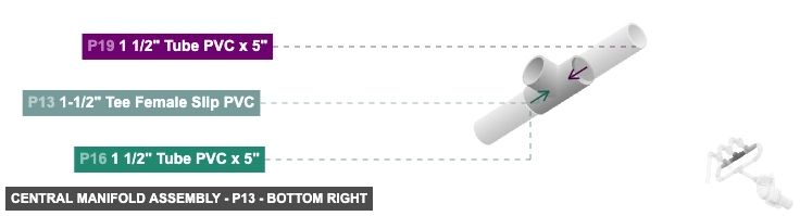
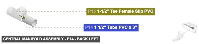
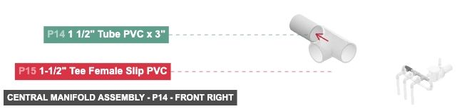
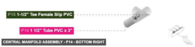
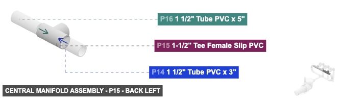
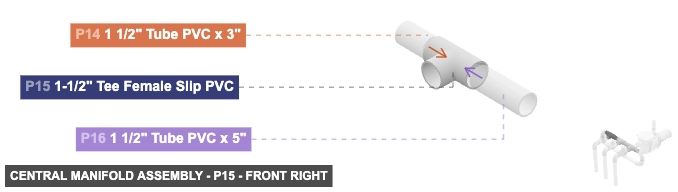
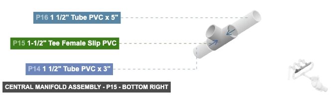
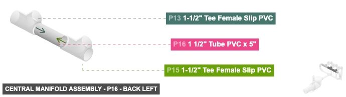
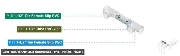
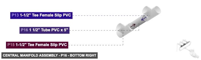
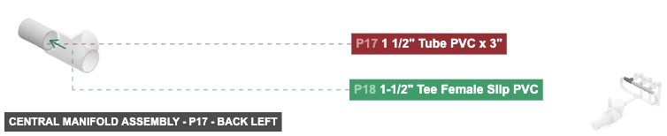
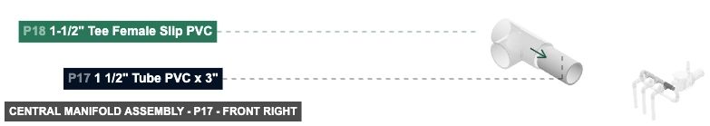
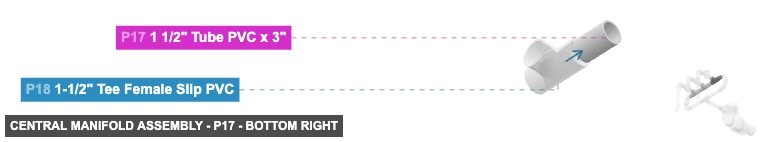
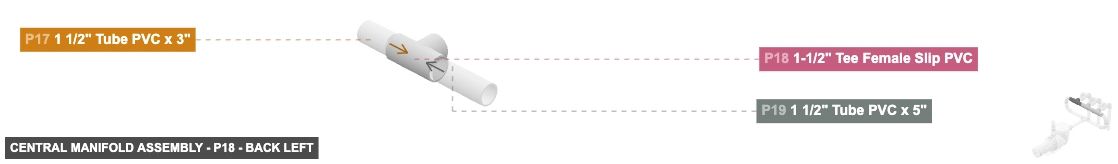
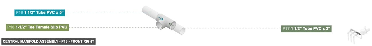
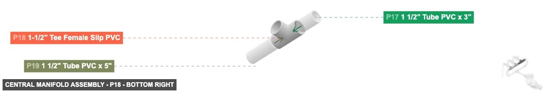
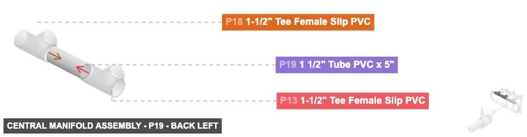
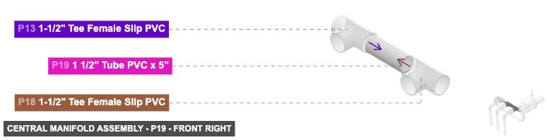
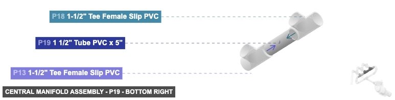
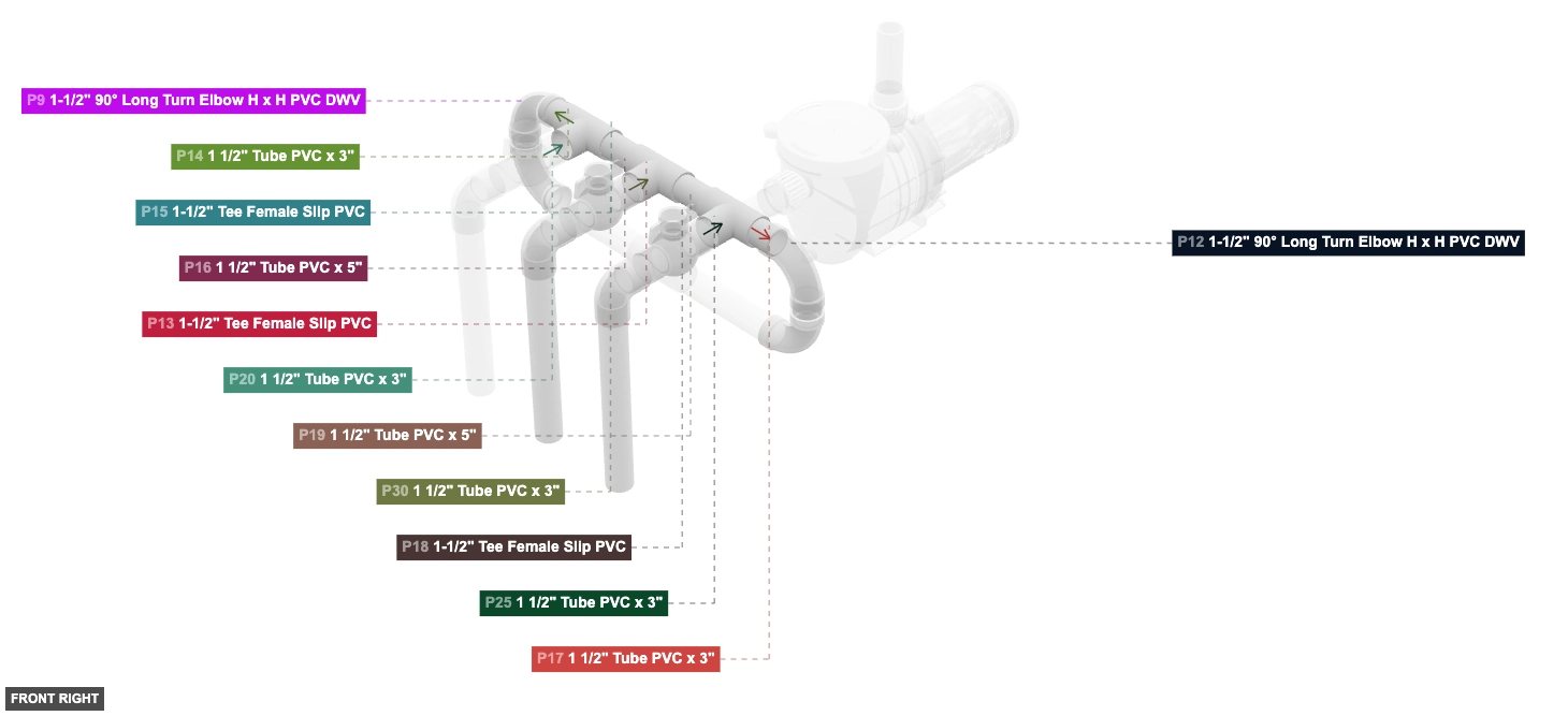
Group: Central Manifold Assembly
To assemble the central distribution manifold that receives flow from both branches and distributes it to three outlets.
First, assemble the Tee backbone: Connect P16's 1.5 inch Male SLIP (one end) to P15's (Tee) 1.5 inch Female SLIP (right side port). Connect P16's 1.5 inch Male SLIP (other end) to P13's (Tee) 1.5 inch Female SLIP (left side port). Then, connect P19's 1.5 inch Male SLIP (one end) to P18's (Tee) 1.5 inch Female SLIP (left side port). Connect P19's 1.5 inch Male SLIP (other end) to P13's (Tee) 1.5 inch Female SLIP (right side port). Next, attach the inlet pipes to the manifold: Connect P14's 1.5 inch Male SLIP (one end, designated as right for connection to P15) to P15's (Tee) 1.5 inch Female SLIP (left side port). Connect P17's 1.5 inch Male SLIP (one end, designated as left for connection to P18) to P18's (Tee) 1.5 inch Female SLIP (right side port).
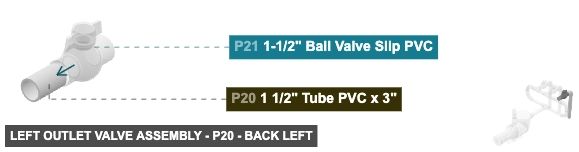
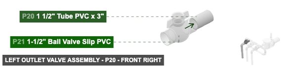
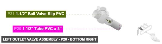
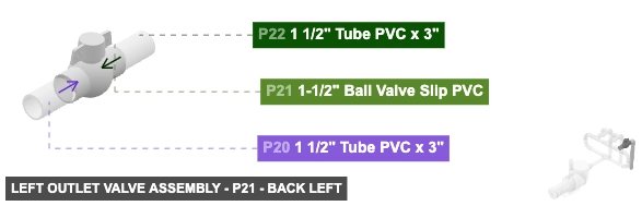
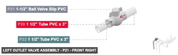
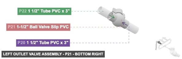
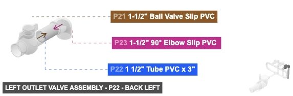
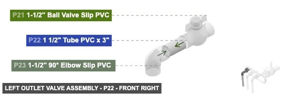
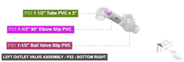
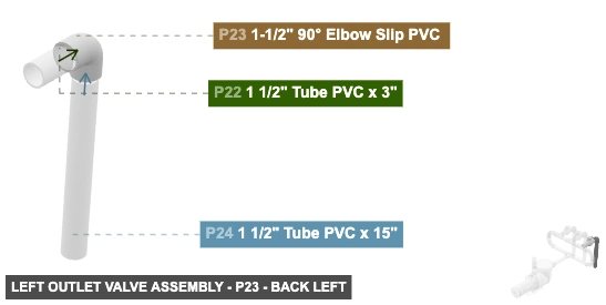
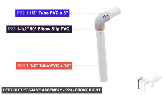
Group: Left Outlet Valve Assembly
To assemble the leftmost valved outlet line extending downwards from the manifold.
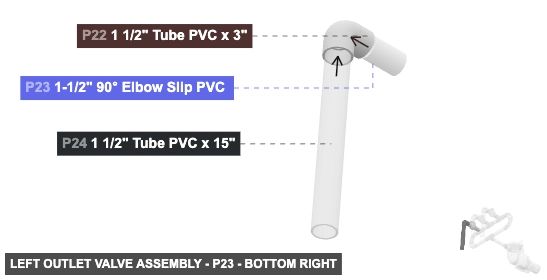
Connect P20's 1.5 inch Male SLIP (front end) to P21's (Ball Valve) 1.5 inch Female SLIP (back port). Connect P22's 1.5 inch Male SLIP (back end) to P21's (Ball Valve) 1.5 inch Female SLIP (front port). Connect P22's 1.5 inch Male SLIP (front end) to P23's (90° Elbow) 1.5 inch Female SLIP (back port). Connect P24's 1.5 inch Male SLIP (top end) to P23's (90° Elbow) 1.5 inch Female SLIP (bottom port).
Phase 3: Inter-Group Assembly
Attaching: Pump and Initial Outlet Pipes
To assemble the main pump and its immediate outlet pipes.
The front-facing 1.5 inch Male SLIP end of P3 from this group will connect to the Main Splitter Assembly (Group 2).
Attaching: Main Splitter and Initial Branches
To create the first split in the water flow and establish two main branches.
Connect this assembly to Group 1 by inserting the front-facing 1.5 inch Male SLIP end of P3 (from Group 1) into P4's (Tee) 1.5 inch Female SLIP (back port). The left-facing 1.5 inch Male SLIP end of P6 and the right-facing 1.5 inch Male SLIP end of P5 will connect to their respective U-Turn Assemblies (Group 3 and Group 4).
Attaching: Left Branch U-Turn Assembly
To redirect the flow from the left branch upwards and towards the central manifold.
Connect this assembly to Group 2 by inserting the left-facing 1.5 inch Male SLIP end of P6 (from Group 2) into P7's (90° Elbow) 1.5 inch Female DWV (right port). The right-facing 1.5 inch Female DWV port of P9 will connect to the Central Manifold Assembly (Group 5).
Angle: back left
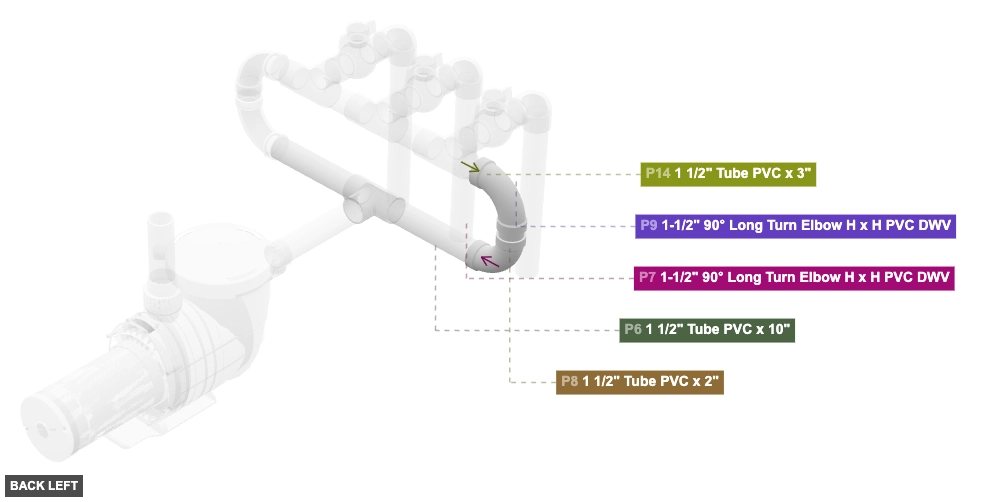
P7 (1.5" 90° Long Turn Elbow H x H PVC DWV) - its 1.5" DWV F #1, which is right-facing, should connect to part 6's 1.5" M SLIP #1, also its 1.5" DWV F #2, which is top-facing, should connect to part 8's 1.5" M SLIP #2
P8 (1.5" Tube PVC 2" length) - its 1.5" M SLIP #1, which is top-facing, should connect to part 9's 1.5" DWV F #1. Additionally, its 1.5" M SLIP #2, which is bottom-facing, should connect to part 7's 1.5" DWV F #2
P9 (1.5" 90° Long Turn Elbow H x H PVC DWV) - its 1.5" DWV F #1, which is bottom-facing, should connect to part 8's 1.5" M SLIP #1, plus its 1.5" DWV F #2, which is right-facing, should connect to part 14's 1.5" M SLIP #2
1-1/2" 90° Long Turn Elbow H x H PVC DWVx 2 1 1/2" Tube PVC x 2"x 1
Angle: front right
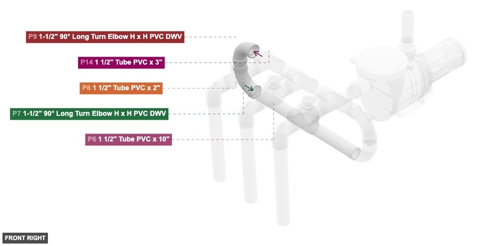
P7 (1.5" 90° Long Turn Elbow H x H PVC DWV) - its 1.5" DWV F #1, which is right-facing, should connect to part 6's 1.5" M SLIP #1, also its 1.5" DWV F #2, which is top-facing, should connect to part 8's 1.5" M SLIP #2
P8 (1.5" Tube PVC 2" length) - its 1.5" M SLIP #1, which is top-facing, should connect to part 9's 1.5" DWV F #1. Additionally, its 1.5" M SLIP #2, which is bottom-facing, should connect to part 7's 1.5" DWV F #2
P9 (1.5" 90° Long Turn Elbow H x H PVC DWV) - its 1.5" DWV F #1, which is bottom-facing, should connect to part 8's 1.5" M SLIP #1, plus its 1.5" DWV F #2, which is right-facing, should connect to part 14's 1.5" M SLIP #2
1-1/2" 90° Long Turn Elbow H x H PVC DWVx 2 1 1/2" Tube PVC x 2"x 1
Angle: bottom right
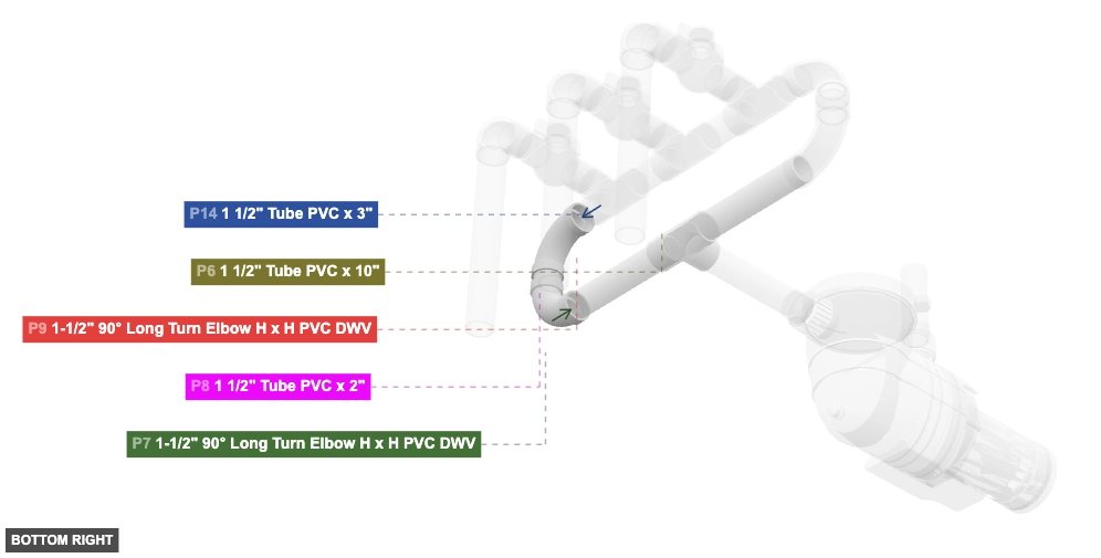
P7 (1.5" 90° Long Turn Elbow H x H PVC DWV) - its 1.5" DWV F #1, which is right-facing, should connect to part 6's 1.5" M SLIP #1, also its 1.5" DWV F #2, which is top-facing, should connect to part 8's 1.5" M SLIP #2
P8 (1.5" Tube PVC 2" length) - its 1.5" M SLIP #1, which is top-facing, should connect to part 9's 1.5" DWV F #1. Additionally, its 1.5" M SLIP #2, which is bottom-facing, should connect to part 7's 1.5" DWV F #2
P9 (1.5" 90° Long Turn Elbow H x H PVC DWV) - its 1.5" DWV F #1, which is bottom-facing, should connect to part 8's 1.5" M SLIP #1, plus its 1.5" DWV F #2, which is right-facing, should connect to part 14's 1.5" M SLIP #2
1-1/2" 90° Long Turn Elbow H x H PVC DWVx 2 1 1/2" Tube PVC x 2"x 1 Attaching: Right Branch U-Turn Assembly
To redirect the flow from the right branch upwards and towards the central manifold.
Connect this assembly to Group 2 by inserting the right-facing 1.5 inch Male SLIP end of P5 (from Group 2) into P10's (90° Elbow) 1.5 inch Female DWV (left port). The left-facing 1.5 inch Female DWV port of P12 will connect to the Central Manifold Assembly (Group 5).
Attaching: Central Manifold Assembly
To assemble the central distribution manifold that receives flow from both branches and distributes it to three outlets.
Connect this manifold to the Left Branch U-Turn Assembly (Group 3) by inserting P14's 1.5 inch Male SLIP (remaining open end, designated as left) into P9's (from Group 3) 1.5 inch Female DWV (right port). Connect this manifold to the Right Branch U-Turn Assembly (Group 4) by inserting P17's 1.5 inch Male SLIP (remaining open end, designated as right) into P12's (from Group 4) 1.5 inch Female DWV (left port). The front-facing 1.5 inch Female SLIP ports on P15, P13, and P18 will connect to the Left, Middle, and Right Outlet Valve Assemblies (Group 6, 7, and 8) respectively.
Angle: back left
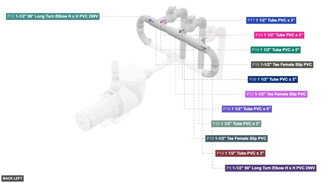
P13 (1.5" Tee F Slip PVC) - attach its 1.5" F SLIP #1 facing left to part 16's 1.5" M SLIP #1, and attach its 1.5" F SLIP #2 facing right to part 19's 1.5" M SLIP #1. Next, connect its 1.5" F SLIP #3 oriented front links with part 30's 1.5" M SLIP #2
P14 (1.5" Tube PVC 3" length) - attach its 1.5" M SLIP #1 facing right to part 15's 1.5" F SLIP #1. Next, connect its 1.5" M SLIP #2 oriented left links with part 9's 1.5" DWV F #2
P15 (1.5" Tee F Slip PVC) - attach its 1.5" F SLIP #1 facing left to part 14's 1.5" M SLIP #1, and attach its 1.5" F SLIP #2 facing right to part 16's 1.5" M SLIP #2. Next, its 1.5" F SLIP #3, which is front-facing, should connect to part 20's 1.5" M SLIP #2
P16 (1.5" Tube PVC 5" length) - connect its 1.5" M SLIP #1 oriented right links with part 13's 1.5" F SLIP #1. Next, attach its 1.5" M SLIP #2 facing left to part 15's 1.5" F SLIP #2
P17 (1.5" Tube PVC 3" length) - attach its 1.5" M SLIP #1 facing left to part 18's 1.5" F SLIP #1. After that, its 1.5" M SLIP #2, which is right-facing, should connect to part 12's 1.5" DWV F #2
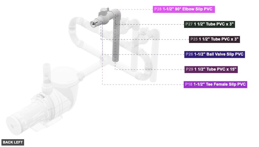
P18 (1.5" Tee F Slip PVC) - attach its 1.5" F SLIP #1 facing right to part 17's 1.5" M SLIP #1, then attach its 1.5" F SLIP #2 facing left to part 19's 1.5" M SLIP #2, then attach its 1.5" F SLIP #3 facing front to part 25's 1.5" M SLIP #2
P19 (1.5" Tube PVC 5" length) - its 1.5" M SLIP #1, which is left-facing, should connect to part 13's 1.5" F SLIP #2. Also, its 1.5" M SLIP #2, which is right-facing, should connect to part 18's 1.5" F SLIP #2
1-1/2" Tee Female Slip PVCx 3 1 1/2" Tube PVC x 3"x 2 1 1/2" Tube PVC x 5"x 2
Angle: front right
P13 (1.5" Tee F Slip PVC) - attach its 1.5" F SLIP #1 facing left to part 16's 1.5" M SLIP #1, and attach its 1.5" F SLIP #2 facing right to part 19's 1.5" M SLIP #1. Next, connect its 1.5" F SLIP #3 oriented front links with part 30's 1.5" M SLIP #2
P14 (1.5" Tube PVC 3" length) - attach its 1.5" M SLIP #1 facing right to part 15's 1.5" F SLIP #1. Next, connect its 1.5" M SLIP #2 oriented left links with part 9's 1.5" DWV F #2
P15 (1.5" Tee F Slip PVC) - attach its 1.5" F SLIP #1 facing left to part 14's 1.5" M SLIP #1, and attach its 1.5" F SLIP #2 facing right to part 16's 1.5" M SLIP #2. Next, its 1.5" F SLIP #3, which is front-facing, should connect to part 20's 1.5" M SLIP #2
P16 (1.5" Tube PVC 5" length) - connect its 1.5" M SLIP #1 oriented right links with part 13's 1.5" F SLIP #1. Next, attach its 1.5" M SLIP #2 facing left to part 15's 1.5" F SLIP #2
P17 (1.5" Tube PVC 3" length) - attach its 1.5" M SLIP #1 facing left to part 18's 1.5" F SLIP #1. After that, its 1.5" M SLIP #2, which is right-facing, should connect to part 12's 1.5" DWV F #2
P18 (1.5" Tee F Slip PVC) - attach its 1.5" F SLIP #1 facing right to part 17's 1.5" M SLIP #1, then attach its 1.5" F SLIP #2 facing left to part 19's 1.5" M SLIP #2, then attach its 1.5" F SLIP #3 facing front to part 25's 1.5" M SLIP #2
P19 (1.5" Tube PVC 5" length) - its 1.5" M SLIP #1, which is left-facing, should connect to part 13's 1.5" F SLIP #2. Also, its 1.5" M SLIP #2, which is right-facing, should connect to part 18's 1.5" F SLIP #2
1-1/2" Tee Female Slip PVCx 3 1 1/2" Tube PVC x 3"x 2 1 1/2" Tube PVC x 5"x 2
Angle: bottom right
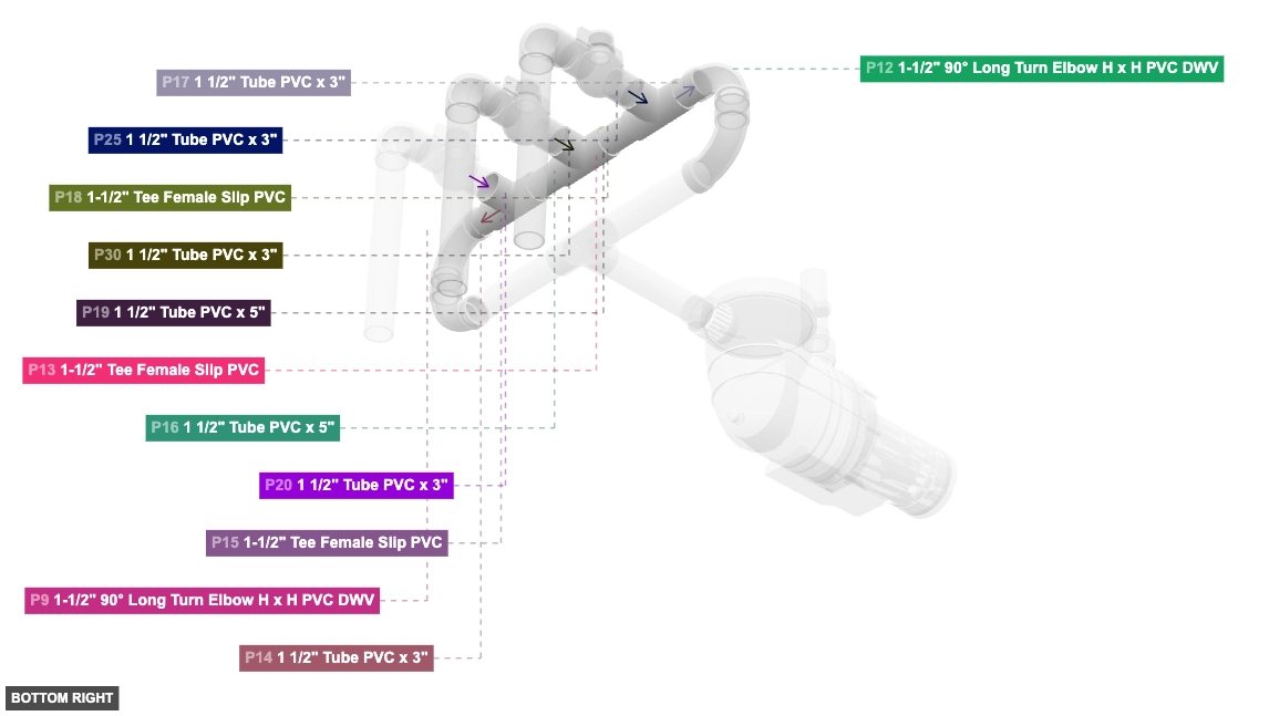
P13 (1.5" Tee F Slip PVC) - attach its 1.5" F SLIP #1 facing left to part 16's 1.5" M SLIP #1, and attach its 1.5" F SLIP #2 facing right to part 19's 1.5" M SLIP #1. Next, connect its 1.5" F SLIP #3 oriented front links with part 30's 1.5" M SLIP #2
P14 (1.5" Tube PVC 3" length) - attach its 1.5" M SLIP #1 facing right to part 15's 1.5" F SLIP #1. Next, connect its 1.5" M SLIP #2 oriented left links with part 9's 1.5" DWV F #2
P15 (1.5" Tee F Slip PVC) - attach its 1.5" F SLIP #1 facing left to part 14's 1.5" M SLIP #1, and attach its 1.5" F SLIP #2 facing right to part 16's 1.5" M SLIP #2. Next, its 1.5" F SLIP #3, which is front-facing, should connect to part 20's 1.5" M SLIP #2
P16 (1.5" Tube PVC 5" length) - connect its 1.5" M SLIP #1 oriented right links with part 13's 1.5" F SLIP #1. Next, attach its 1.5" M SLIP #2 facing left to part 15's 1.5" F SLIP #2
P17 (1.5" Tube PVC 3" length) - attach its 1.5" M SLIP #1 facing left to part 18's 1.5" F SLIP #1. After that, its 1.5" M SLIP #2, which is right-facing, should connect to part 12's 1.5" DWV F #2
P18 (1.5" Tee F Slip PVC) - attach its 1.5" F SLIP #1 facing right to part 17's 1.5" M SLIP #1, then attach its 1.5" F SLIP #2 facing left to part 19's 1.5" M SLIP #2, then attach its 1.5" F SLIP #3 facing front to part 25's 1.5" M SLIP #2
P19 (1.5" Tube PVC 5" length) - its 1.5" M SLIP #1, which is left-facing, should connect to part 13's 1.5" F SLIP #2. Also, its 1.5" M SLIP #2, which is right-facing, should connect to part 18's 1.5" F SLIP #2
1-1/2" Tee Female Slip PVCx 3 1 1/2" Tube PVC x 3"x 2 1 1/2" Tube PVC x 5"x 2 Attaching: Left Outlet Valve Assembly
To assemble the leftmost valved outlet line extending downwards from the manifold.
Connect this assembly to the Central Manifold Assembly (Group 5) by inserting P20's 1.5 inch Male SLIP (back end) into P15's (Tee from Group 5) 1.5 inch Female SLIP (front port).
Angle: back left
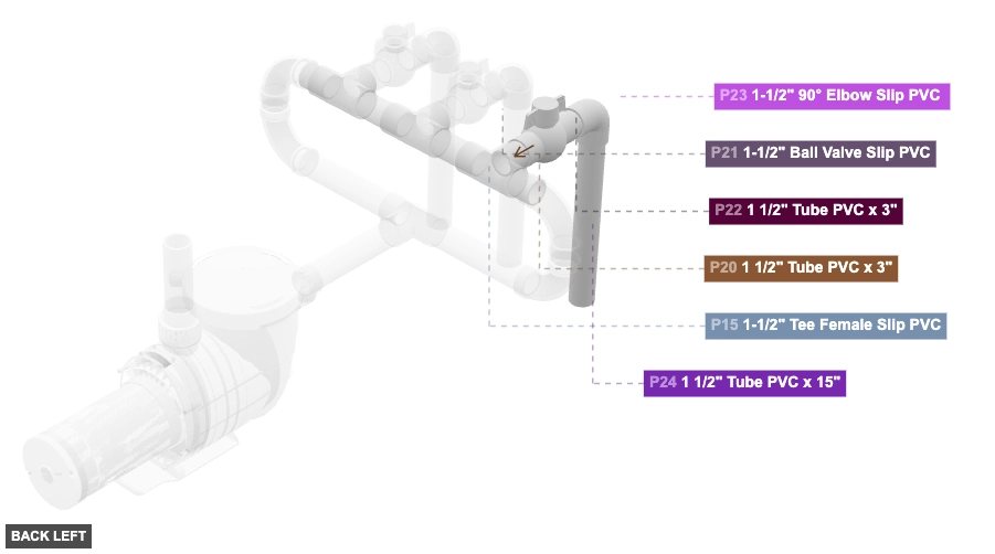
P20 (1.5" Tube PVC 3" length) - attach its 1.5" M SLIP #1 facing front to part 21's 1.5" F SLIP #1, plus attach its 1.5" M SLIP #2 facing back to part 15's 1.5" F SLIP #3
P21 (1.5" Ball Valve Slip PVC) - its 1.5" F SLIP #1, which is back-facing, should connect to part 20's 1.5" M SLIP #1. Additionally, attach its 1.5" F SLIP #2 facing front to part 22's 1.5" M SLIP #2
P22 (1.5" Tube PVC 3" length) - connect its 1.5" M SLIP #1 oriented front links with part 23's 1.5" F SLIP #1. After that, attach its 1.5" M SLIP #2 facing back to part 21's 1.5" F SLIP #2
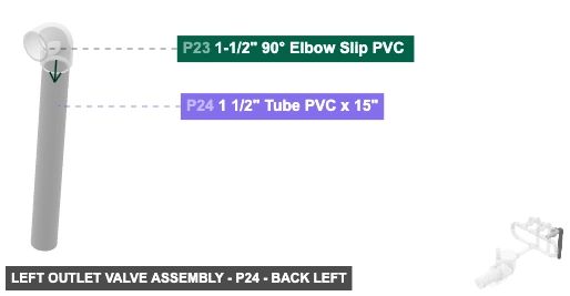
P23 (1.5" 90° Elbow Slip PVC ) - its 1.5" F SLIP #1, which is back-facing, should connect to part 22's 1.5" M SLIP #1, and its 1.5" F SLIP #2, which is bottom-facing, should connect to part 24's 1.5" M SLIP #2
P24 (1.5" Tube PVC 15" length) - attach its 1.5" M SLIP #2 facing top to part 23's 1.5" F SLIP #2, also its 1.5" M SLIP #1 must be oriented bottom
1 1/2" Tube PVC x 3"x 2 1-1/2" Ball Valve Slip PVCx 1 1-1/2" 90° Elbow Slip PVC x 1 1 1/2" Tube PVC x 15"x 1
Angle: front right
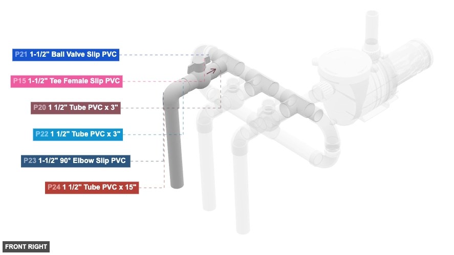
P20 (1.5" Tube PVC 3" length) - attach its 1.5" M SLIP #1 facing front to part 21's 1.5" F SLIP #1, plus attach its 1.5" M SLIP #2 facing back to part 15's 1.5" F SLIP #3
P21 (1.5" Ball Valve Slip PVC) - its 1.5" F SLIP #1, which is back-facing, should connect to part 20's 1.5" M SLIP #1. Additionally, attach its 1.5" F SLIP #2 facing front to part 22's 1.5" M SLIP #2
P22 (1.5" Tube PVC 3" length) - connect its 1.5" M SLIP #1 oriented front links with part 23's 1.5" F SLIP #1. After that, attach its 1.5" M SLIP #2 facing back to part 21's 1.5" F SLIP #2
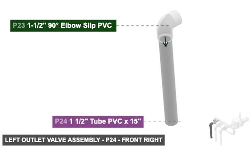
P23 (1.5" 90° Elbow Slip PVC ) - its 1.5" F SLIP #1, which is back-facing, should connect to part 22's 1.5" M SLIP #1, and its 1.5" F SLIP #2, which is bottom-facing, should connect to part 24's 1.5" M SLIP #2
P24 (1.5" Tube PVC 15" length) - attach its 1.5" M SLIP #2 facing top to part 23's 1.5" F SLIP #2, also its 1.5" M SLIP #1 must be oriented bottom
1 1/2" Tube PVC x 3"x 2 1-1/2" Ball Valve Slip PVCx 1 1-1/2" 90° Elbow Slip PVC x 1 1 1/2" Tube PVC x 15"x 1
Angle: bottom right
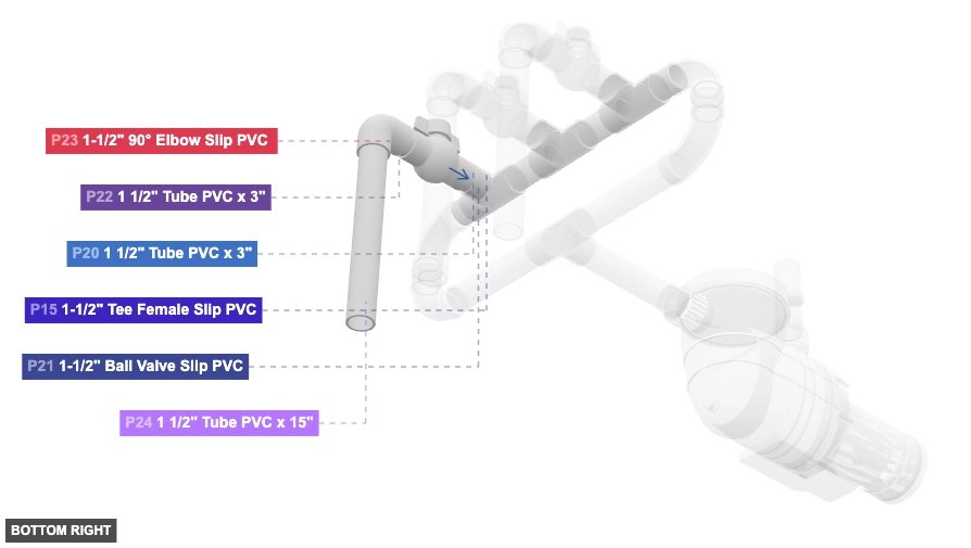
P20 (1.5" Tube PVC 3" length) - attach its 1.5" M SLIP #1 facing front to part 21's 1.5" F SLIP #1, plus attach its 1.5" M SLIP #2 facing back to part 15's 1.5" F SLIP #3
P21 (1.5" Ball Valve Slip PVC) - its 1.5" F SLIP #1, which is back-facing, should connect to part 20's 1.5" M SLIP #1. Additionally, attach its 1.5" F SLIP #2 facing front to part 22's 1.5" M SLIP #2
P22 (1.5" Tube PVC 3" length) - connect its 1.5" M SLIP #1 oriented front links with part 23's 1.5" F SLIP #1. After that, attach its 1.5" M SLIP #2 facing back to part 21's 1.5" F SLIP #2
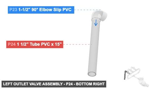
P23 (1.5" 90° Elbow Slip PVC ) - its 1.5" F SLIP #1, which is back-facing, should connect to part 22's 1.5" M SLIP #1, and its 1.5" F SLIP #2, which is bottom-facing, should connect to part 24's 1.5" M SLIP #2
P24 (1.5" Tube PVC 15" length) - attach its 1.5" M SLIP #2 facing top to part 23's 1.5" F SLIP #2, also its 1.5" M SLIP #1 must be oriented bottom
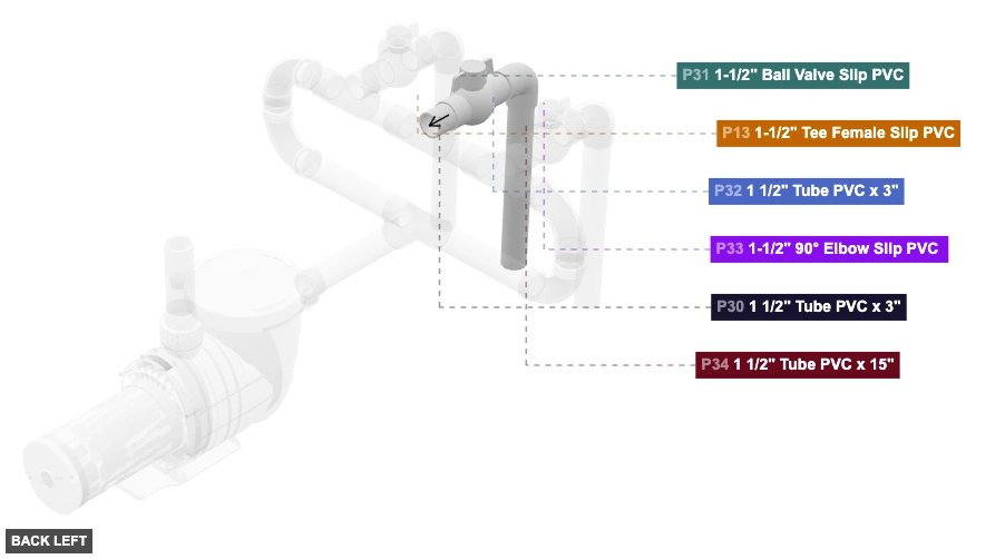
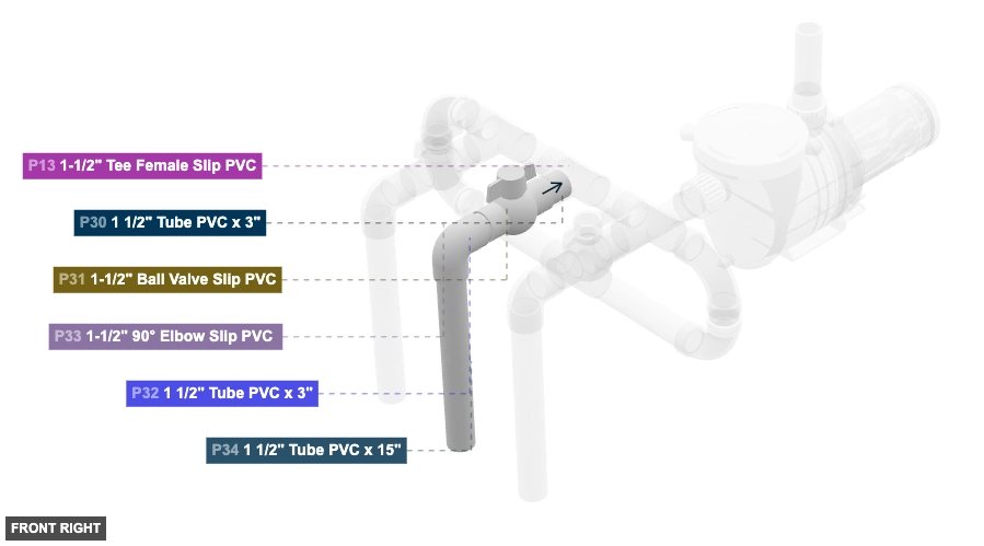
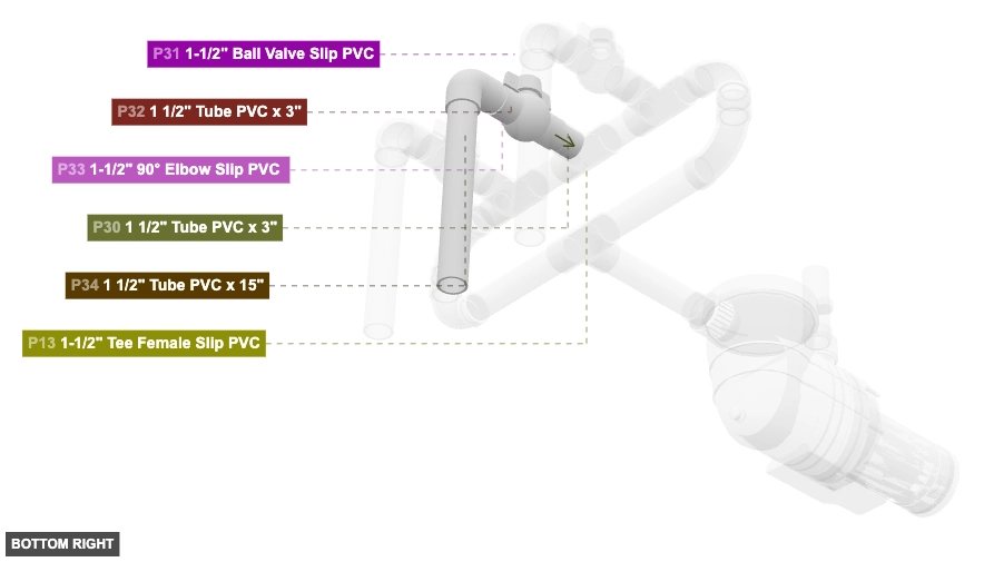
1 1/2" Tube PVC x 3"x 2 1-1/2" Ball Valve Slip PVCx 1 1-1/2" 90° Elbow Slip PVC x 1 1 1/2" Tube PVC x 15"x 1 Attaching: Middle Outlet Valve Assembly
To assemble the middle valved outlet line extending downwards from the manifold.
Connect this assembly to the Central Manifold Assembly (Group 5) by inserting P30's 1.5 inch Male SLIP (back end) into P13's (Tee from Group 5) 1.5 inch Female SLIP (front port).
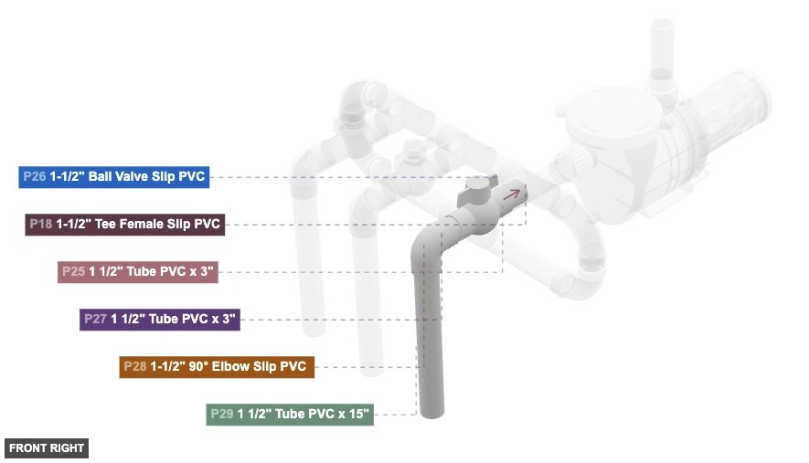
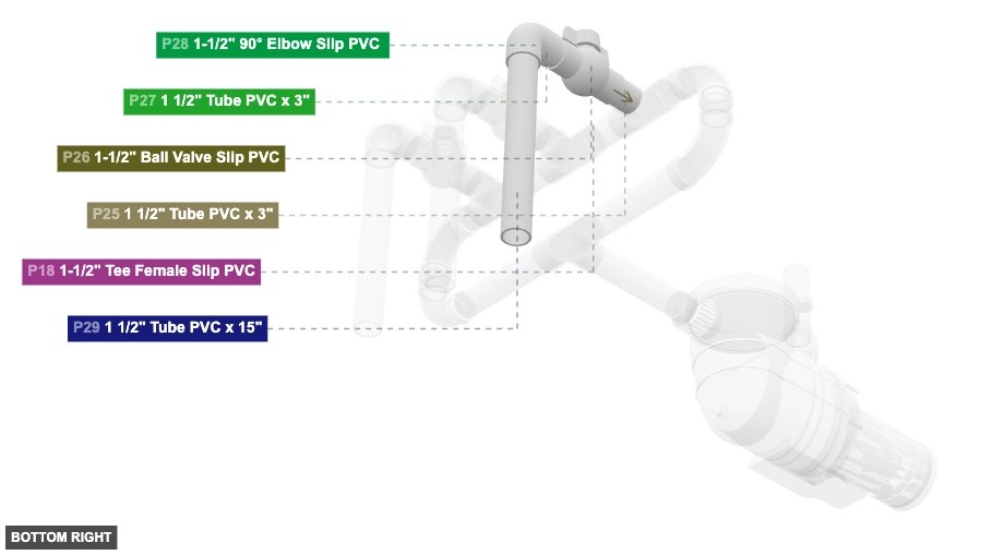
Attaching: Right Outlet Valve Assembly
To assemble the rightmost valved outlet line extending downwards from the manifold.
Connect this assembly to the Central Manifold Assembly (Group 5) by inserting P25's 1.5 inch Male SLIP (back end) into P18's (Tee from Group 5) 1.5 inch Female SLIP (front port).