Kayak Cart - Comprehensive Assembly Plan And Visual Guide
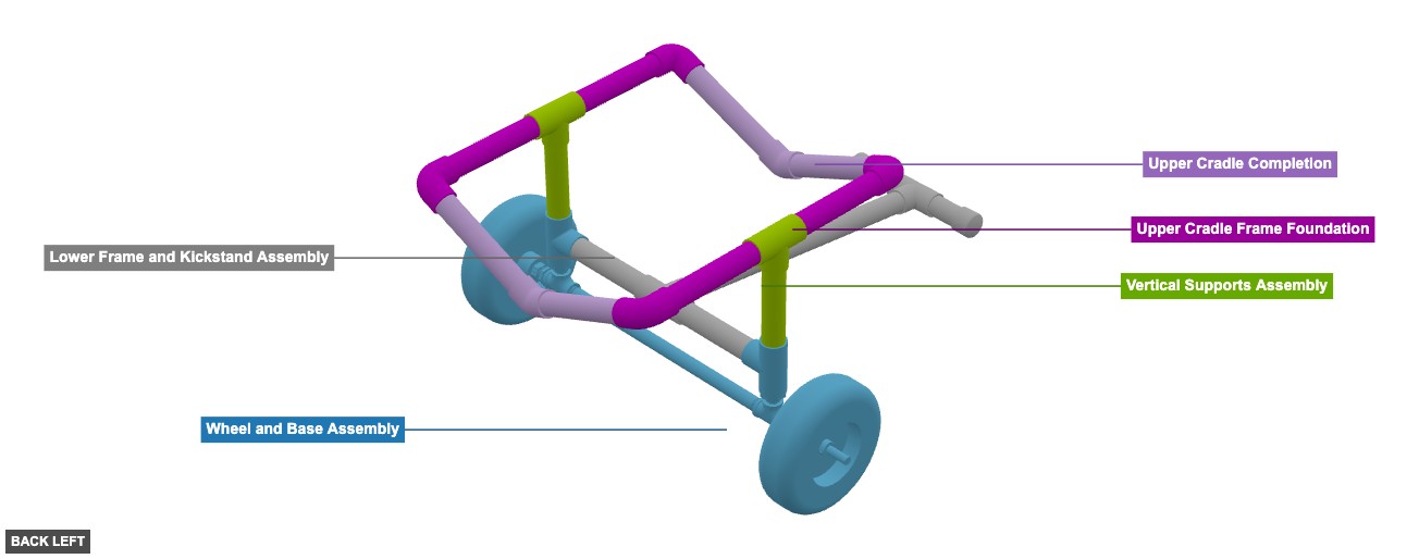
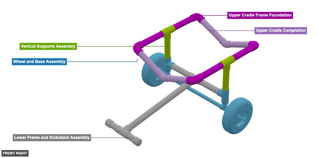
A wheeled cart, constructed primarily from PVC pipes and fittings, designed to transport a kayak. It features a lower frame with wheels, a front kickstand, and an upper cradle structure. - Kayak Cart
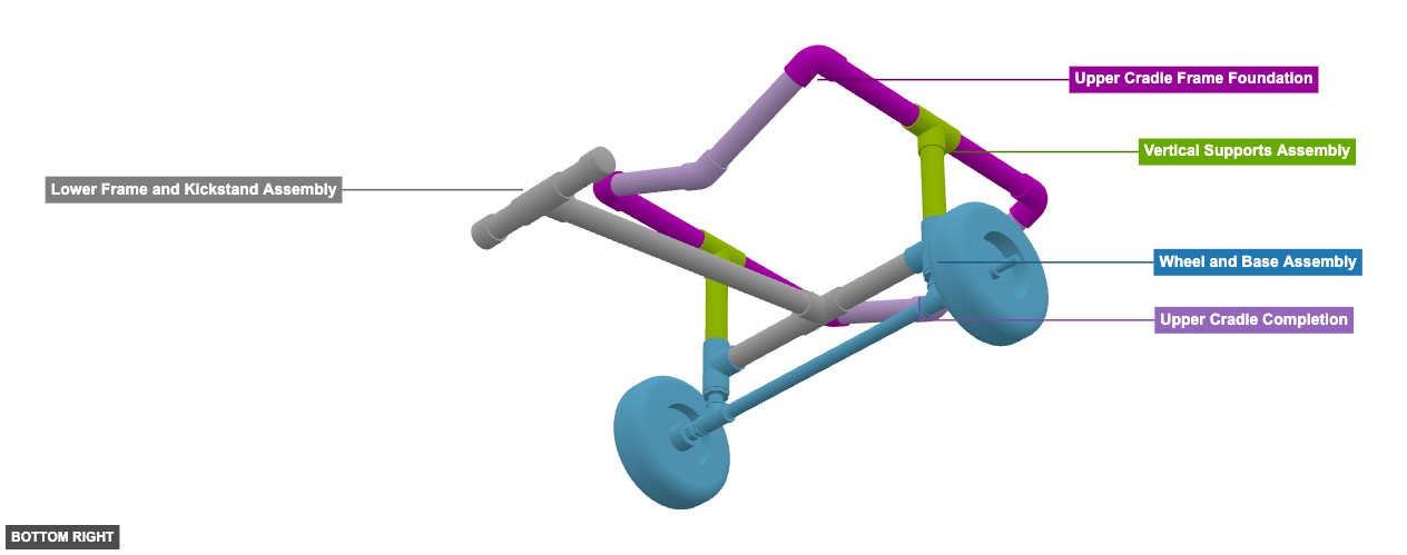
Phase 1: Group Overview
Angle: back left
Wheel and Base Assembly
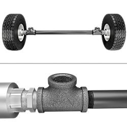 10" Cart Wheels With 36" Long x 3/4" Diameter and Tee Black Steel Connectionx 1
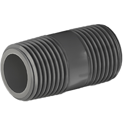 3/4" x 2" Nipplex 2
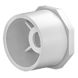 3/4" x 1-1/4" Bushing Male Slip PVCx 2
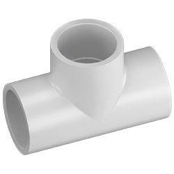 1-1/4" Tee Female Slip PVCx 2
Lower Frame and Kickstand Assembly
1-1/4" Tee Female Slip PVCx 2  1 1/4" Tube x 25"x 1
1 1/4" Tube x 5"x 2  1-1/4" Cap Slip PVCx 2
1 1/4" Tube x 9"x 1 1 1/4" Tube x 9.21"x 1 Vertical Supports Assembly
1 1/4" Tube x 8.68"x 2 1-1/4" Tee Female Slip PVCx 2 Upper Cradle Frame Foundation
1 1/4" Tube x 10"x 4  1-1/4" 90° Elbow Slip PVC x 4
Upper Cradle Completion
1 1/4" Tube x 10.2"x 1  1-1/4" 45° Elbow Slip PVCx 2
1 1/4" Tube x 10.3"x 1 1 1/4" Tube x 10.48"x 1 1 1/4" Tube x 10.66"x 1
Angle: front right
Wheel and Base Assembly
10" Cart Wheels With 36" Long x 3/4" Diameter and Tee Black Steel Connectionx 1 3/4" x 2" Nipplex 2 3/4" x 1-1/4" Bushing Male Slip PVCx 2 1-1/4" Tee Female Slip PVCx 2 Lower Frame and Kickstand Assembly
1-1/4" Tee Female Slip PVCx 2 1 1/4" Tube x 25"x 1 1 1/4" Tube x 5"x 2 1-1/4" Cap Slip PVCx 2 1 1/4" Tube x 9"x 1 1 1/4" Tube x 9.21"x 1 Vertical Supports Assembly
1 1/4" Tube x 8.68"x 2 1-1/4" Tee Female Slip PVCx 2 Upper Cradle Frame Foundation
1 1/4" Tube x 10"x 4 1-1/4" 90° Elbow Slip PVC x 4 Upper Cradle Completion
1 1/4" Tube x 10.2"x 1 1-1/4" 45° Elbow Slip PVCx 2 1 1/4" Tube x 10.3"x 1 1 1/4" Tube x 10.48"x 1 1 1/4" Tube x 10.66"x 1
Angle: bottom right
Wheel and Base Assembly
10" Cart Wheels With 36" Long x 3/4" Diameter and Tee Black Steel Connectionx 1 3/4" x 2" Nipplex 2 3/4" x 1-1/4" Bushing Male Slip PVCx 2 1-1/4" Tee Female Slip PVCx 2 Lower Frame and Kickstand Assembly
1-1/4" Tee Female Slip PVCx 2 1 1/4" Tube x 25"x 1 1 1/4" Tube x 5"x 2 1-1/4" Cap Slip PVCx 2 1 1/4" Tube x 9"x 1 1 1/4" Tube x 9.21"x 1 Vertical Supports Assembly
1 1/4" Tube x 8.68"x 2 1-1/4" Tee Female Slip PVCx 2 Upper Cradle Frame Foundation
1 1/4" Tube x 10"x 4 1-1/4" 90° Elbow Slip PVC x 4 Upper Cradle Completion
1 1/4" Tube x 10.2"x 1 1-1/4" 45° Elbow Slip PVCx 2 1 1/4" Tube x 10.3"x 1 1 1/4" Tube x 10.48"x 1 1 1/4" Tube x 10.66"x 1 Phase 2: Individual Group Assembly
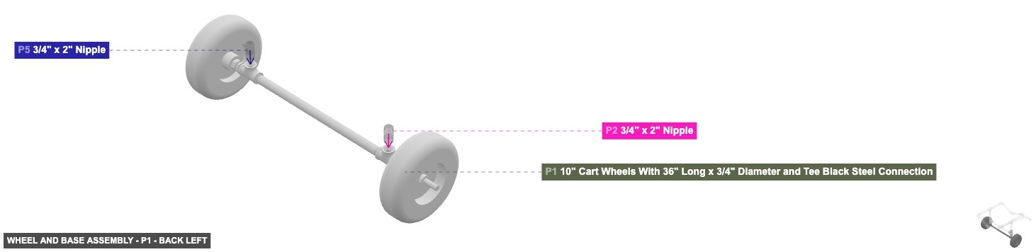
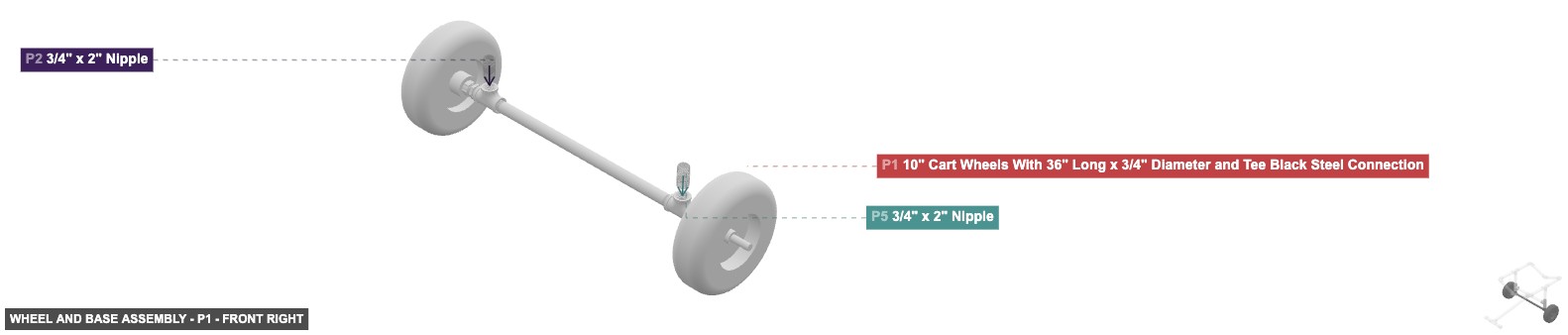
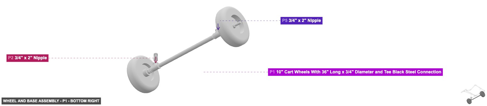
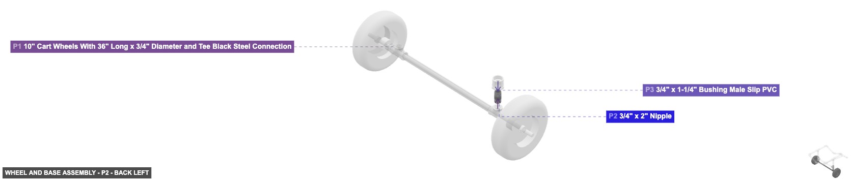
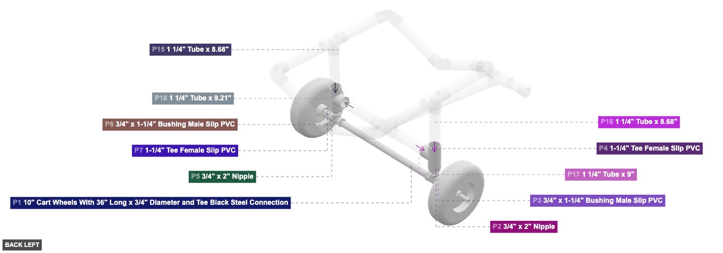
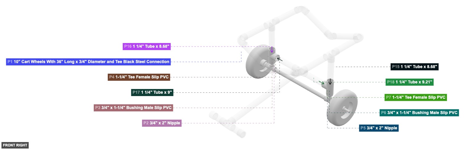
Group: Wheel and Base Assembly
Forms the base with wheels and the initial vertical connection points for the frame.
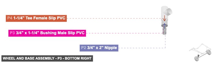
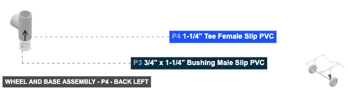
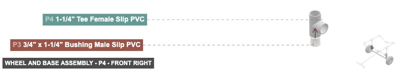
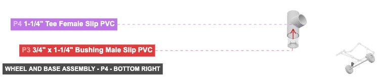
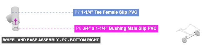
1. Take P1 (Wheels/Axle Tee). 2. Connect the 0.75" Male Threaded end of P2 (Nipple) to a 0.75" Female Threaded connection on P1. 3. Connect the 0.75" Male Threaded end of P5 (Nipple) to the other 0.75" Female Threaded connection on P1. 4. Connect the 0.75" Female Threaded end of P3 (Bushing) to the top 0.75" Male Threaded end of P2. 5. Connect the 0.75" Female Threaded end of P6 (Bushing) to the top 0.75" Male Threaded end of P5. 6. Connect the bottom 1.25" Female SLIP connection of P4 (Tee) to the top 1.25" Male SLIP end of P3. 7. Connect the bottom 1.25" Female SLIP connection of P7 (Tee) to the top 1.25" Male SLIP end of P6.
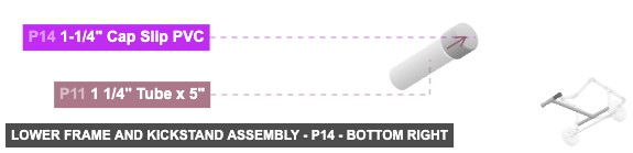
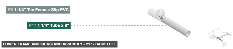
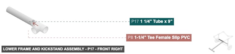
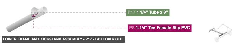
Group: Lower Frame and Kickstand Assembly
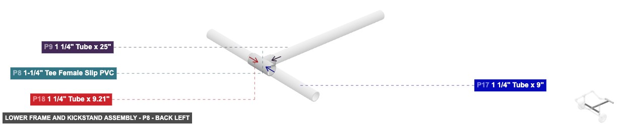
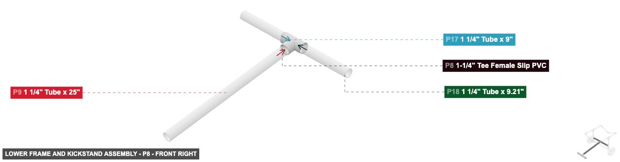
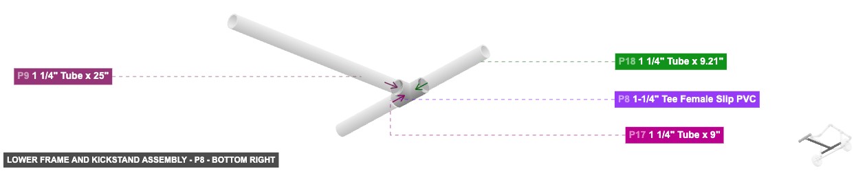
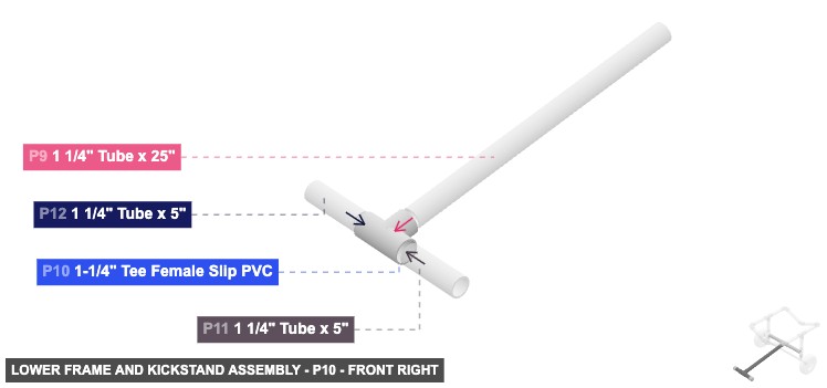
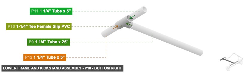
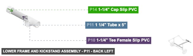
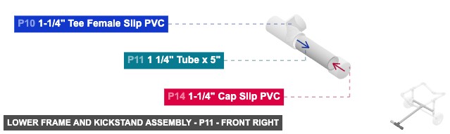
Creates the horizontal structure connecting the two wheel assemblies and forms the front kickstand.
1. Connect one 1.25" Male SLIP end of P17 (Tube 9") to the side 1.25" Female SLIP connection on P4 (from Group 1). 2. Connect the other 1.25" Male SLIP end of P17 to the left-facing 1.25" Female SLIP connection on P8 (Tee). 3. Connect one 1.25" Male SLIP end of P18 (Tube 9.21") to the side 1.25" Female SLIP connection on P7 (from Group 1). 4. Connect the other 1.25" Male SLIP end of P18 to the right-facing 1.25" Female SLIP connection on P8. 5. Connect the back 1.25" Male SLIP end of P9 (Tube 25") to the front-facing 1.25" Female SLIP connection on P8. 6. Connect the front 1.25" Male SLIP end of P9 to the back-facing 1.25" Female SLIP connection on P10 (Tee). 7. Connect the left 1.25" Male SLIP end of P11 (Tube 5") to the right-facing 1.25" Female SLIP connection on P10. 8. Connect the right 1.25" Male SLIP end of P11 to the 1.25" Female SLIP connection on P14 (Cap). 9. Connect the right 1.25" Male SLIP end of P12 (Tube 5") to the left-facing 1.25" Female SLIP connection on P10. 10. Connect the left 1.25" Male SLIP end of P12 to the 1.25" Female SLIP connection on P13 (Cap).
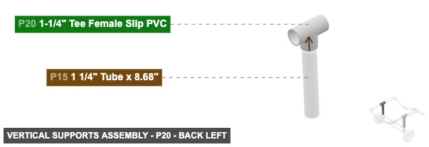
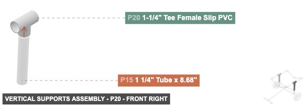
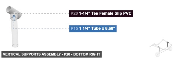
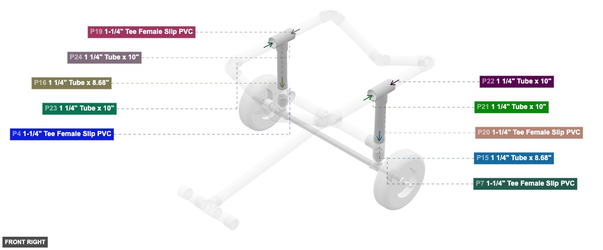
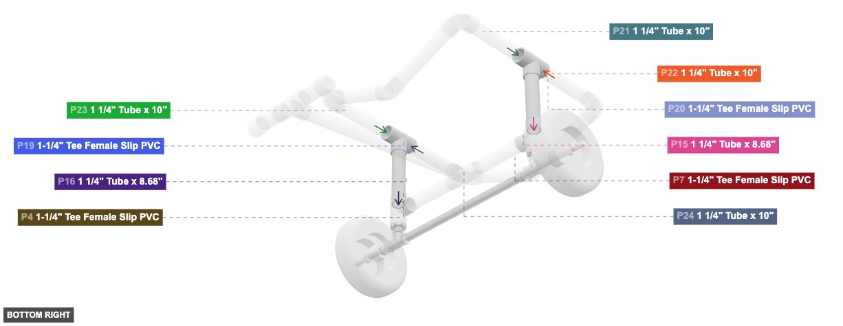
Group: Vertical Supports Assembly
Adds the main vertical supports extending upwards from the base assembly.
1. Connect the bottom 1.25" Male SLIP end of P16 (Tube 8.68") to the top 1.25" Female SLIP connection on P4 (from Group 1). 2. Connect the top 1.25" Male SLIP end of P16 to the bottom 1.25" Female SLIP connection on P19 (Tee). 3. Connect the bottom 1.25" Male SLIP end of P15 (Tube 8.68") to the top 1.25" Female SLIP connection on P7 (from Group 1). 4. Connect the top 1.25" Male SLIP end of P15 to the bottom 1.25" Female SLIP connection on P20 (Tee).
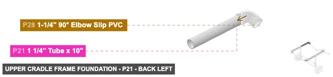
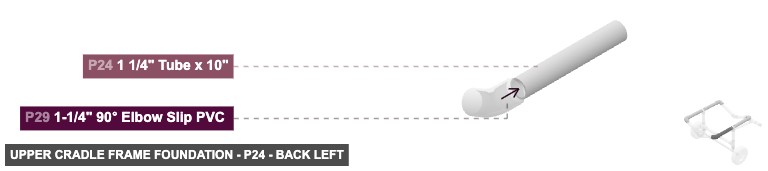
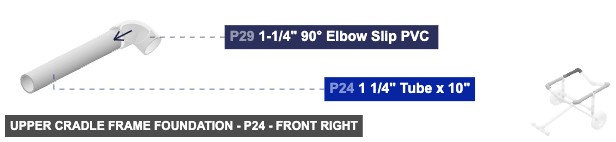
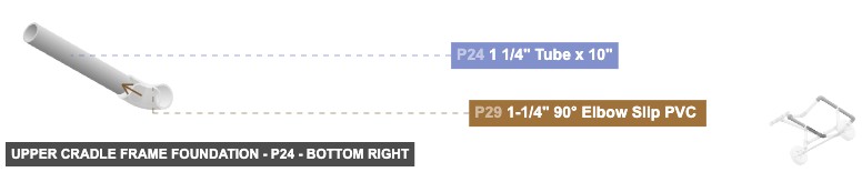
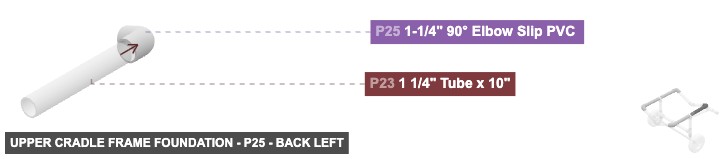
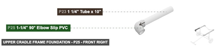
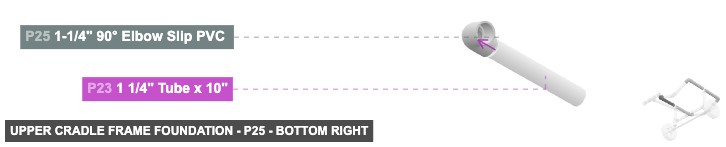
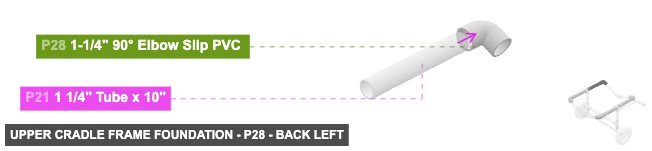
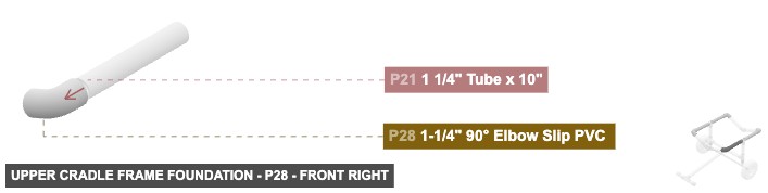
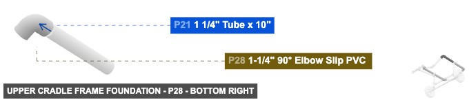
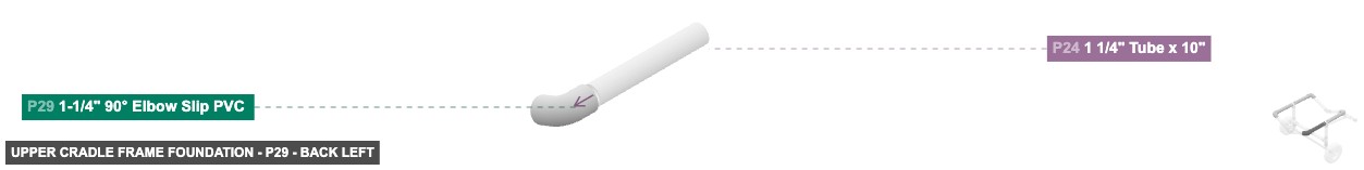
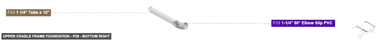
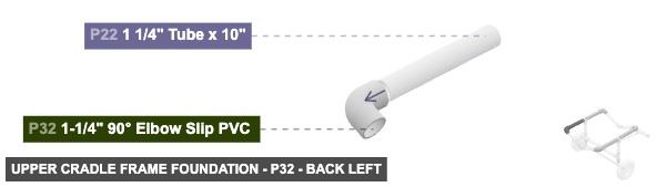
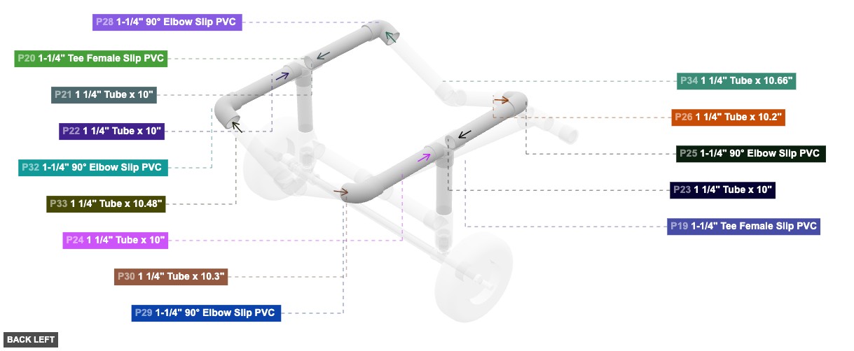
Group: Upper Cradle Frame Foundation
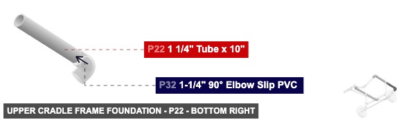
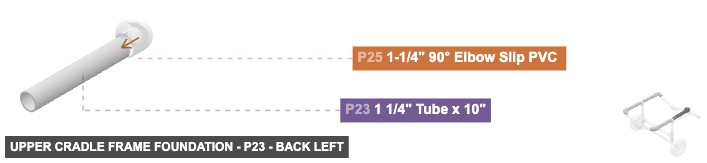
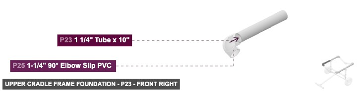
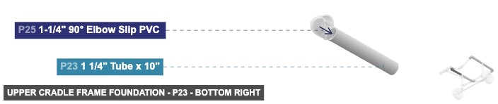
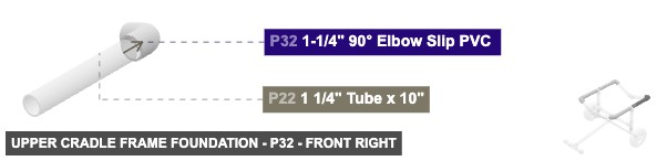
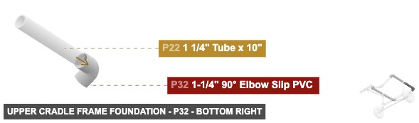
Builds the front, back, and initial corner pieces of the upper kayak cradle.
1. Connect the back 1.25" Male SLIP end of P23 (Tube 10") to the front-facing 1.25" Female SLIP connection on P19 (from Group 3). 2. Connect the front 1.25" Male SLIP end of P23 to the back-facing 1.25" Female SLIP connection on P25 (90 Elbow). 3. Connect the back 1.25" Male SLIP end of P21 (Tube 10") to the front-facing 1.25" Female SLIP connection on P20 (from Group 3). 4. Connect the front 1.25" Male SLIP end of P21 to the back-facing 1.25" Female SLIP connection on P28 (90 Elbow). 5. Connect the front 1.25" Male SLIP end of P24 (Tube 10") to the back-facing 1.25" Female SLIP connection on P19 (from Group 3). 6. Connect the back 1.25" Male SLIP end of P24 to the front-facing 1.25" Female SLIP connection on P29 (90 Elbow). 7. Connect the front 1.25" Male SLIP end of P22 (Tube 10") to the back-facing 1.25" Female SLIP connection on P20 (from Group 3). 8. Connect the back 1.25" Male SLIP end of P22 to the front-facing 1.25" Female SLIP connection on P32 (90 Elbow).
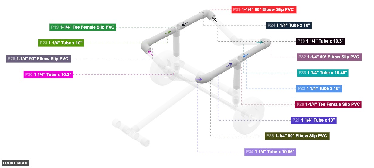
Group: Upper Cradle Completion
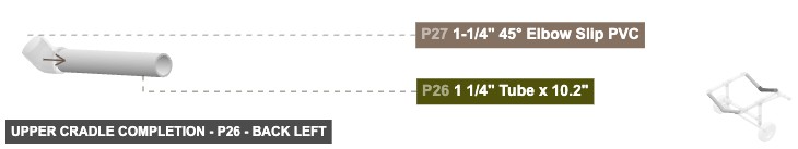
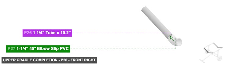
Completes the upper kayak cradle by adding side tubes and angled connectors.
1. Connect the left 1.25" Male SLIP end of P26 (Tube 10.2") to the side 1.25" Female SLIP connection on P25 (from Group 4). 2. Connect the right 1.25" Male SLIP end of P26 to the left-facing 1.25" Female SLIP connection on P27 (45 Elbow). 3. Connect the right 1.25" Male SLIP end of P34 (Tube 10.66") to the side 1.25" Female SLIP connection on P28 (from Group 4). 4. Connect the left 1.25" Male SLIP end of P34 to the right-facing 1.25" Female SLIP connection on P27. 5. Connect the left 1.25" Male SLIP end of P30 (Tube 10.3") to the side 1.25" Female SLIP connection on P29 (from Group 4). 6. Connect the right 1.25" Male SLIP end of P30 to the left-facing 1.25" Female SLIP connection on P31 (45 Elbow). 7. Connect the right 1.25" Male SLIP end of P33 (Tube 10.48") to the side 1.25" Female SLIP connection on P32 (from Group 4). 8. Connect the left 1.25" Male SLIP end of P33 to the right-facing 1.25" Female SLIP connection on P31.
Phase 3: Inter-Group Assembly
Attaching: Wheel and Base Assembly
Forms the base with wheels and the initial vertical connection points for the frame.
This assembly forms the base. It will connect horizontally to the Lower Frame (Group 2) and vertically to the Vertical Supports (Group 3).
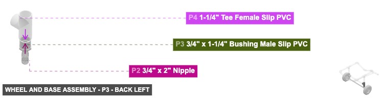
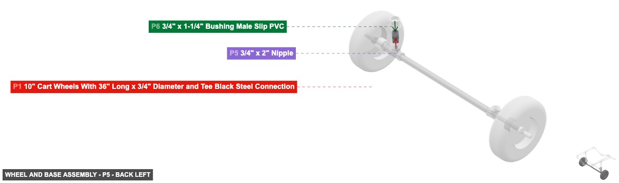
Angle: back left
P1 (10" Cart Wheels With 36" Long x 3/4" Diameter and Tee Black Steel Connection) - its 0.75" F Threaded #1, which is top-facing, should connect to part 2's 0.75" M Threaded #1. After that, connect its 0.75" F Threaded #2 oriented top links with part 5's 0.75" M Threaded #1
P2 (0.75" x 2" Nipple) - its 0.75" M Threaded #1, which is bottom-facing, should connect to part 1's 0.75" F Threaded #1. Additionally, attach its 0.75" M Threaded #2 facing top to part 3's 0.75" F Threaded #1
P3 (0.75" x 1-1/4" Bushing M Slip PVC) - connect its 0.75" F Threaded #1 oriented bottom links with part 2's 0.75" M Threaded #2. Next, connect its 1.25" M SLIP #1 oriented top links with part 4's 1.25" F SLIP #1
P4 (1.25" Tee F Slip PVC) - its 1.25" F SLIP #1, which is bottom-facing, should connect to part 3's 1.25" M SLIP #1, and connect its 1.25" F SLIP #2 oriented top links with part 16's 1.25" M SLIP #2, plus connect its 1.25" F SLIP #3 oriented right links with part 17's 1.25" M SLIP #2
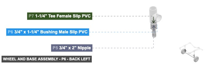
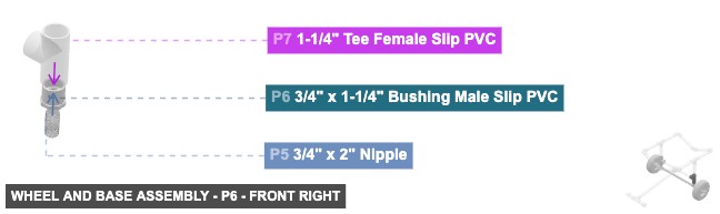
P5 (0.75" x 2" Nipple) - its 0.75" M Threaded #1, which is bottom-facing, should connect to part 1's 0.75" F Threaded #2. After that, connect its 0.75" M Threaded #2 oriented top links with part 6's 0.75" F Threaded #1
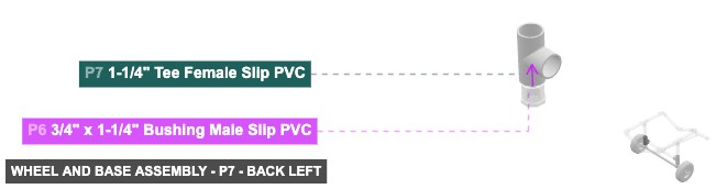
P6 (0.75" x 1-1/4" Bushing M Slip PVC) - its 0.75" F Threaded #1, which is bottom-facing, should connect to part 5's 0.75" M Threaded #2. After that, its 1.25" M SLIP #1, which is top-facing, should connect to part 7's 1.25" F SLIP #1
P7 (1.25" Tee F Slip PVC) - its 1.25" F SLIP #1, which is bottom-facing, should connect to part 6's 1.25" M SLIP #1, plus connect its 1.25" F SLIP #2 oriented top links with part 15's 1.25" M SLIP #2, plus connect its 1.25" F SLIP #3 oriented left links with part 18's 1.25" M SLIP #2
10" Cart Wheels With 36" Long x 3/4" Diameter and Tee Black Steel Connectionx 1 3/4" x 2" Nipplex 2 3/4" x 1-1/4" Bushing Male Slip PVCx 2 1-1/4" Tee Female Slip PVCx 2
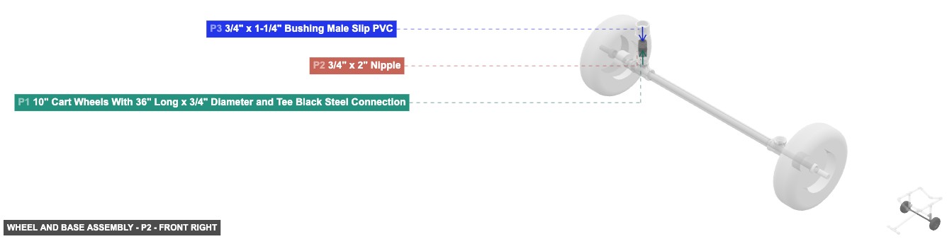
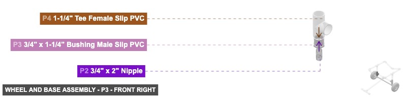
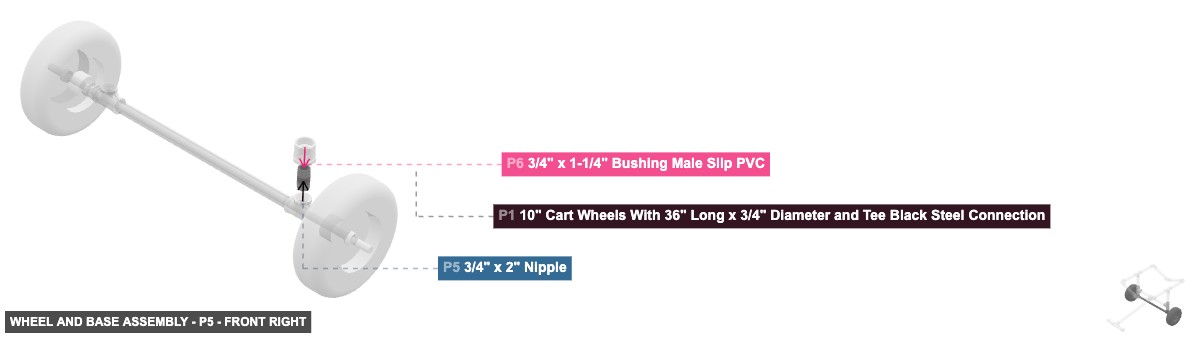
Angle: front right
P1 (10" Cart Wheels With 36" Long x 3/4" Diameter and Tee Black Steel Connection) - its 0.75" F Threaded #1, which is top-facing, should connect to part 2's 0.75" M Threaded #1. After that, connect its 0.75" F Threaded #2 oriented top links with part 5's 0.75" M Threaded #1
P2 (0.75" x 2" Nipple) - its 0.75" M Threaded #1, which is bottom-facing, should connect to part 1's 0.75" F Threaded #1. Additionally, attach its 0.75" M Threaded #2 facing top to part 3's 0.75" F Threaded #1
P3 (0.75" x 1-1/4" Bushing M Slip PVC) - connect its 0.75" F Threaded #1 oriented bottom links with part 2's 0.75" M Threaded #2. Next, connect its 1.25" M SLIP #1 oriented top links with part 4's 1.25" F SLIP #1
P4 (1.25" Tee F Slip PVC) - its 1.25" F SLIP #1, which is bottom-facing, should connect to part 3's 1.25" M SLIP #1, and connect its 1.25" F SLIP #2 oriented top links with part 16's 1.25" M SLIP #2, plus connect its 1.25" F SLIP #3 oriented right links with part 17's 1.25" M SLIP #2
P5 (0.75" x 2" Nipple) - its 0.75" M Threaded #1, which is bottom-facing, should connect to part 1's 0.75" F Threaded #2. After that, connect its 0.75" M Threaded #2 oriented top links with part 6's 0.75" F Threaded #1
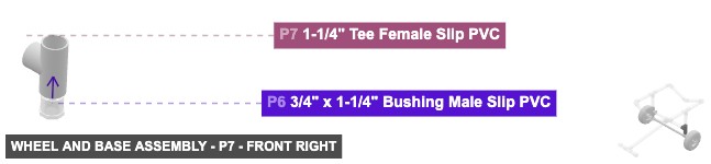
P6 (0.75" x 1-1/4" Bushing M Slip PVC) - its 0.75" F Threaded #1, which is bottom-facing, should connect to part 5's 0.75" M Threaded #2. After that, its 1.25" M SLIP #1, which is top-facing, should connect to part 7's 1.25" F SLIP #1
P7 (1.25" Tee F Slip PVC) - its 1.25" F SLIP #1, which is bottom-facing, should connect to part 6's 1.25" M SLIP #1, plus connect its 1.25" F SLIP #2 oriented top links with part 15's 1.25" M SLIP #2, plus connect its 1.25" F SLIP #3 oriented left links with part 18's 1.25" M SLIP #2
10" Cart Wheels With 36" Long x 3/4" Diameter and Tee Black Steel Connectionx 1 3/4" x 2" Nipplex 2 3/4" x 1-1/4" Bushing Male Slip PVCx 2 1-1/4" Tee Female Slip PVCx 2
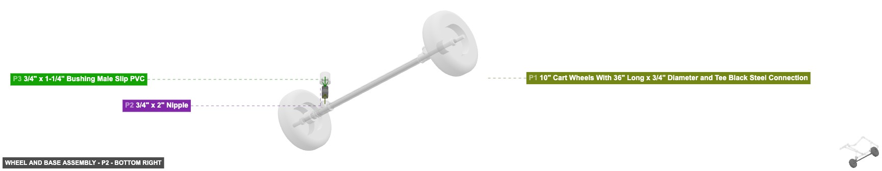
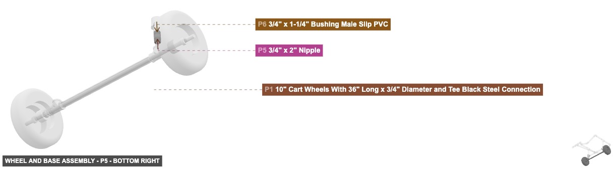
Angle: bottom right

P1 (10" Cart Wheels With 36" Long x 3/4" Diameter and Tee Black Steel Connection) - its 0.75" F Threaded #1, which is top-facing, should connect to part 2's 0.75" M Threaded #1. After that, connect its 0.75" F Threaded #2 oriented top links with part 5's 0.75" M Threaded #1
P2 (0.75" x 2" Nipple) - its 0.75" M Threaded #1, which is bottom-facing, should connect to part 1's 0.75" F Threaded #1. Additionally, attach its 0.75" M Threaded #2 facing top to part 3's 0.75" F Threaded #1
P3 (0.75" x 1-1/4" Bushing M Slip PVC) - connect its 0.75" F Threaded #1 oriented bottom links with part 2's 0.75" M Threaded #2. Next, connect its 1.25" M SLIP #1 oriented top links with part 4's 1.25" F SLIP #1
P4 (1.25" Tee F Slip PVC) - its 1.25" F SLIP #1, which is bottom-facing, should connect to part 3's 1.25" M SLIP #1, and connect its 1.25" F SLIP #2 oriented top links with part 16's 1.25" M SLIP #2, plus connect its 1.25" F SLIP #3 oriented right links with part 17's 1.25" M SLIP #2
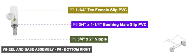
P5 (0.75" x 2" Nipple) - its 0.75" M Threaded #1, which is bottom-facing, should connect to part 1's 0.75" F Threaded #2. After that, connect its 0.75" M Threaded #2 oriented top links with part 6's 0.75" F Threaded #1
P6 (0.75" x 1-1/4" Bushing M Slip PVC) - its 0.75" F Threaded #1, which is bottom-facing, should connect to part 5's 0.75" M Threaded #2. After that, its 1.25" M SLIP #1, which is top-facing, should connect to part 7's 1.25" F SLIP #1
P7 (1.25" Tee F Slip PVC) - its 1.25" F SLIP #1, which is bottom-facing, should connect to part 6's 1.25" M SLIP #1, plus connect its 1.25" F SLIP #2 oriented top links with part 15's 1.25" M SLIP #2, plus connect its 1.25" F SLIP #3 oriented left links with part 18's 1.25" M SLIP #2
10" Cart Wheels With 36" Long x 3/4" Diameter and Tee Black Steel Connectionx 1 3/4" x 2" Nipplex 2 3/4" x 1-1/4" Bushing Male Slip PVCx 2 1-1/4" Tee Female Slip PVCx 2 Attaching: Lower Frame and Kickstand Assembly
Creates the horizontal structure connecting the two wheel assemblies and forms the front kickstand.
Attach this Lower Frame and Kickstand assembly horizontally between the two base connectors (P4, P7) from Group 1.
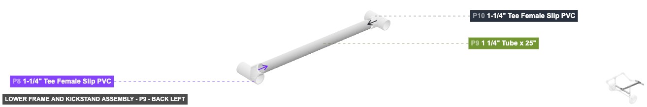
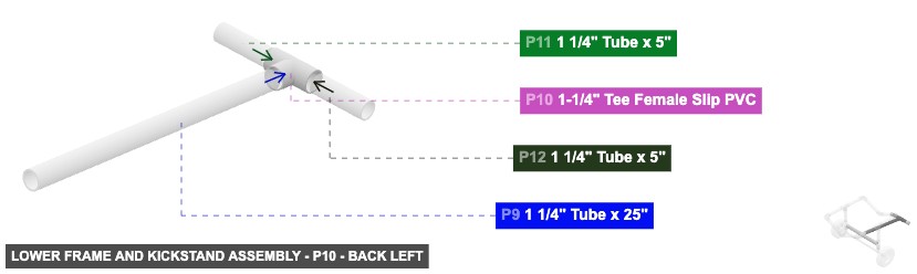
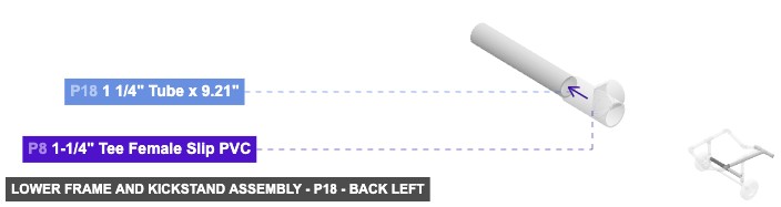
Angle: back left
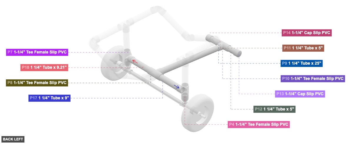
P8 (1.25" Tee F Slip PVC) - connect its 1.25" F SLIP #1 oriented left links with part 17's 1.25" M SLIP #1, also its 1.25" F SLIP #2, which is right-facing, should connect to part 18's 1.25" M SLIP #1, plus its 1.25" F SLIP #3, which is front-facing, should connect to part 9's 1.25" M SLIP #2
P9 (1.25" Tube 25" length) - connect its 1.25" M SLIP #1 oriented front links with part 10's 1.25" F SLIP #3, then attach its 1.25" M SLIP #2 facing back to part 8's 1.25" F SLIP #3
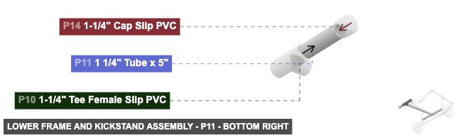
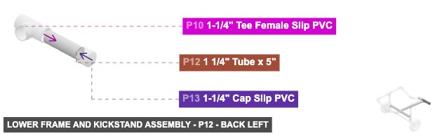
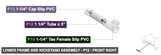
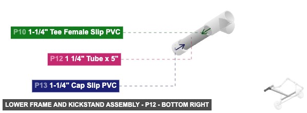
P10 (1.25" Tee F Slip PVC) - its 1.25" F SLIP #1, which is left-facing, should connect to part 12's 1.25" M SLIP #2, plus its 1.25" F SLIP #2, which is right-facing, should connect to part 11's 1.25" M SLIP #2, then connect its 1.25" F SLIP #3 oriented back links with part 9's 1.25" M SLIP #1
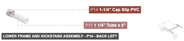
P11 (1.25" Tube 5" length) - its 1.25" M SLIP #1, which is right-facing, should connect to part 14's 1.25" F SLIP #1. Additionally, connect its 1.25" M SLIP #2 oriented left links with part 10's 1.25" F SLIP #2
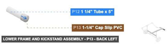
P12 (1.25" Tube 5" length) - attach its 1.25" M SLIP #1 facing left to part 13's 1.25" F SLIP #1. Next, attach its 1.25" M SLIP #2 facing right to part 10's 1.25" F SLIP #1
P13 (1.25" Cap Slip PVC) - attach its 1.25" F SLIP #1 facing right to part 12's 1.25" M SLIP #1
P14 (1.25" Cap Slip PVC) - attach its 1.25" F SLIP #1 facing left to part 11's 1.25" M SLIP #1
P17 (1.25" Tube 9" length) - connect its 1.25" M SLIP #1 oriented right links with part 8's 1.25" F SLIP #1, and connect its 1.25" M SLIP #2 oriented left links with part 4's 1.25" F SLIP #3
P18 (1.25" Tube 9.21" length) - its 1.25" M SLIP #1, which is left-facing, should connect to part 8's 1.25" F SLIP #2, plus attach its 1.25" M SLIP #2 facing right to part 7's 1.25" F SLIP #3
1-1/4" Tee Female Slip PVCx 2 1 1/4" Tube x 25"x 1 1 1/4" Tube x 5"x 2 1-1/4" Cap Slip PVCx 2 1 1/4" Tube x 9"x 1 1 1/4" Tube x 9.21"x 1
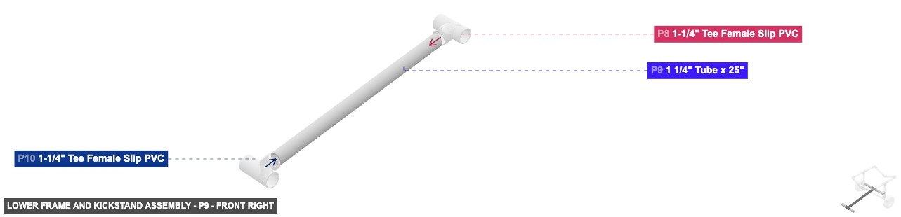
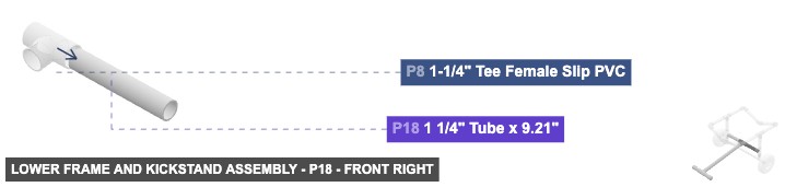
Angle: front right
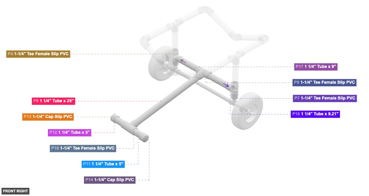
P8 (1.25" Tee F Slip PVC) - connect its 1.25" F SLIP #1 oriented left links with part 17's 1.25" M SLIP #1, also its 1.25" F SLIP #2, which is right-facing, should connect to part 18's 1.25" M SLIP #1, plus its 1.25" F SLIP #3, which is front-facing, should connect to part 9's 1.25" M SLIP #2
P9 (1.25" Tube 25" length) - connect its 1.25" M SLIP #1 oriented front links with part 10's 1.25" F SLIP #3, then attach its 1.25" M SLIP #2 facing back to part 8's 1.25" F SLIP #3
P10 (1.25" Tee F Slip PVC) - its 1.25" F SLIP #1, which is left-facing, should connect to part 12's 1.25" M SLIP #2, plus its 1.25" F SLIP #2, which is right-facing, should connect to part 11's 1.25" M SLIP #2, then connect its 1.25" F SLIP #3 oriented back links with part 9's 1.25" M SLIP #1
P11 (1.25" Tube 5" length) - its 1.25" M SLIP #1, which is right-facing, should connect to part 14's 1.25" F SLIP #1. Additionally, connect its 1.25" M SLIP #2 oriented left links with part 10's 1.25" F SLIP #2
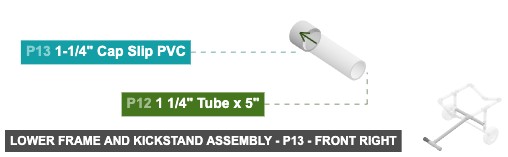
P12 (1.25" Tube 5" length) - attach its 1.25" M SLIP #1 facing left to part 13's 1.25" F SLIP #1. Next, attach its 1.25" M SLIP #2 facing right to part 10's 1.25" F SLIP #1
P13 (1.25" Cap Slip PVC) - attach its 1.25" F SLIP #1 facing right to part 12's 1.25" M SLIP #1
P14 (1.25" Cap Slip PVC) - attach its 1.25" F SLIP #1 facing left to part 11's 1.25" M SLIP #1
P17 (1.25" Tube 9" length) - connect its 1.25" M SLIP #1 oriented right links with part 8's 1.25" F SLIP #1, and connect its 1.25" M SLIP #2 oriented left links with part 4's 1.25" F SLIP #3
P18 (1.25" Tube 9.21" length) - its 1.25" M SLIP #1, which is left-facing, should connect to part 8's 1.25" F SLIP #2, plus attach its 1.25" M SLIP #2 facing right to part 7's 1.25" F SLIP #3
1-1/4" Tee Female Slip PVCx 2 1 1/4" Tube x 25"x 1 1 1/4" Tube x 5"x 2 1-1/4" Cap Slip PVCx 2 1 1/4" Tube x 9"x 1 1 1/4" Tube x 9.21"x 1
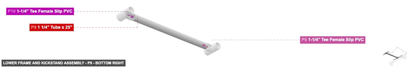
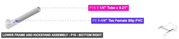
Angle: bottom right
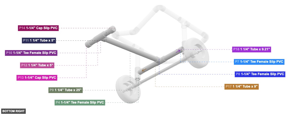
P8 (1.25" Tee F Slip PVC) - connect its 1.25" F SLIP #1 oriented left links with part 17's 1.25" M SLIP #1, also its 1.25" F SLIP #2, which is right-facing, should connect to part 18's 1.25" M SLIP #1, plus its 1.25" F SLIP #3, which is front-facing, should connect to part 9's 1.25" M SLIP #2
P9 (1.25" Tube 25" length) - connect its 1.25" M SLIP #1 oriented front links with part 10's 1.25" F SLIP #3, then attach its 1.25" M SLIP #2 facing back to part 8's 1.25" F SLIP #3
P10 (1.25" Tee F Slip PVC) - its 1.25" F SLIP #1, which is left-facing, should connect to part 12's 1.25" M SLIP #2, plus its 1.25" F SLIP #2, which is right-facing, should connect to part 11's 1.25" M SLIP #2, then connect its 1.25" F SLIP #3 oriented back links with part 9's 1.25" M SLIP #1
P11 (1.25" Tube 5" length) - its 1.25" M SLIP #1, which is right-facing, should connect to part 14's 1.25" F SLIP #1. Additionally, connect its 1.25" M SLIP #2 oriented left links with part 10's 1.25" F SLIP #2
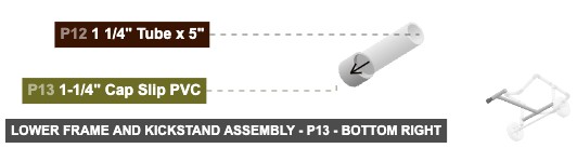
P12 (1.25" Tube 5" length) - attach its 1.25" M SLIP #1 facing left to part 13's 1.25" F SLIP #1. Next, attach its 1.25" M SLIP #2 facing right to part 10's 1.25" F SLIP #1
P13 (1.25" Cap Slip PVC) - attach its 1.25" F SLIP #1 facing right to part 12's 1.25" M SLIP #1
P14 (1.25" Cap Slip PVC) - attach its 1.25" F SLIP #1 facing left to part 11's 1.25" M SLIP #1
P17 (1.25" Tube 9" length) - connect its 1.25" M SLIP #1 oriented right links with part 8's 1.25" F SLIP #1, and connect its 1.25" M SLIP #2 oriented left links with part 4's 1.25" F SLIP #3
P18 (1.25" Tube 9.21" length) - its 1.25" M SLIP #1, which is left-facing, should connect to part 8's 1.25" F SLIP #2, plus attach its 1.25" M SLIP #2 facing right to part 7's 1.25" F SLIP #3
1-1/4" Tee Female Slip PVCx 2 1 1/4" Tube x 25"x 1 1 1/4" Tube x 5"x 2 1-1/4" Cap Slip PVCx 2 1 1/4" Tube x 9"x 1 1 1/4" Tube x 9.21"x 1 Attaching: Vertical Supports Assembly
Adds the main vertical supports extending upwards from the base assembly.
Attach these Vertical Supports onto the top connections of the Base Assembly (P4, P7 from Group 1).
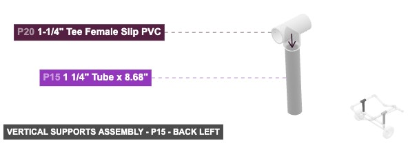
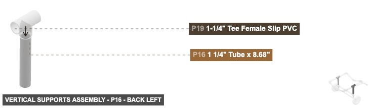
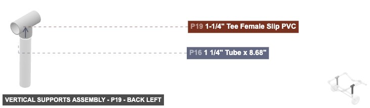
Angle: back left
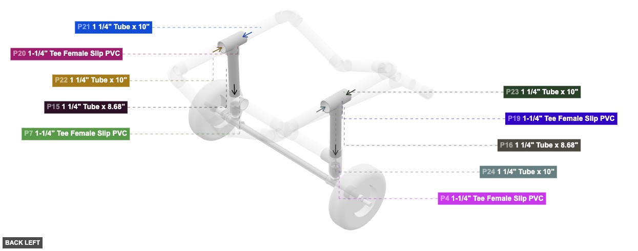
P15 (1.25" Tube 8.68" length) - connect its 1.25" M SLIP #1 oriented top links with part 20's 1.25" F SLIP #3. Also, connect its 1.25" M SLIP #2 oriented bottom links with part 7's 1.25" F SLIP #2
P16 (1.25" Tube 8.68" length) - its 1.25" M SLIP #1, which is top-facing, should connect to part 19's 1.25" F SLIP #3. Next, attach its 1.25" M SLIP #2 facing bottom to part 4's 1.25" F SLIP #2
P19 (1.25" Tee F Slip PVC) - connect its 1.25" F SLIP #1 oriented back links with part 24's 1.25" M SLIP #2. After that, connect its 1.25" F SLIP #2 oriented front links with part 23's 1.25" M SLIP #2. Additionally, connect its 1.25" F SLIP #3 oriented bottom links with part 16's 1.25" M SLIP #1
P20 (1.25" Tee F Slip PVC) - its 1.25" F SLIP #1, which is back-facing, should connect to part 22's 1.25" M SLIP #2, also its 1.25" F SLIP #2, which is front-facing, should connect to part 21's 1.25" M SLIP #2, and connect its 1.25" F SLIP #3 oriented bottom links with part 15's 1.25" M SLIP #1
1 1/4" Tube x 8.68"x 2 1-1/4" Tee Female Slip PVCx 2
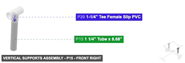
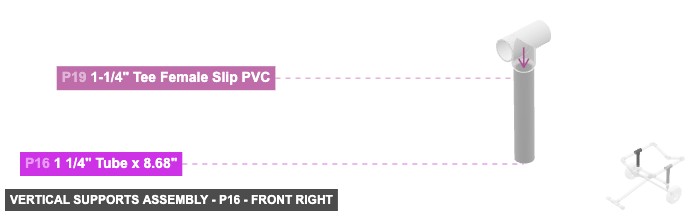
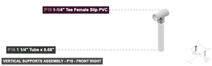
Angle: front right
P15 (1.25" Tube 8.68" length) - connect its 1.25" M SLIP #1 oriented top links with part 20's 1.25" F SLIP #3. Also, connect its 1.25" M SLIP #2 oriented bottom links with part 7's 1.25" F SLIP #2
P16 (1.25" Tube 8.68" length) - its 1.25" M SLIP #1, which is top-facing, should connect to part 19's 1.25" F SLIP #3. Next, attach its 1.25" M SLIP #2 facing bottom to part 4's 1.25" F SLIP #2
P19 (1.25" Tee F Slip PVC) - connect its 1.25" F SLIP #1 oriented back links with part 24's 1.25" M SLIP #2. After that, connect its 1.25" F SLIP #2 oriented front links with part 23's 1.25" M SLIP #2. Additionally, connect its 1.25" F SLIP #3 oriented bottom links with part 16's 1.25" M SLIP #1
P20 (1.25" Tee F Slip PVC) - its 1.25" F SLIP #1, which is back-facing, should connect to part 22's 1.25" M SLIP #2, also its 1.25" F SLIP #2, which is front-facing, should connect to part 21's 1.25" M SLIP #2, and connect its 1.25" F SLIP #3 oriented bottom links with part 15's 1.25" M SLIP #1
1 1/4" Tube x 8.68"x 2 1-1/4" Tee Female Slip PVCx 2
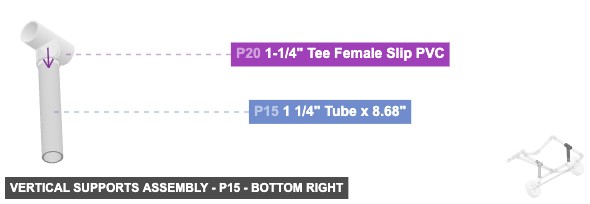
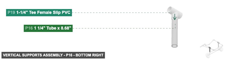
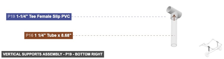
Angle: bottom right
P15 (1.25" Tube 8.68" length) - connect its 1.25" M SLIP #1 oriented top links with part 20's 1.25" F SLIP #3. Also, connect its 1.25" M SLIP #2 oriented bottom links with part 7's 1.25" F SLIP #2
P16 (1.25" Tube 8.68" length) - its 1.25" M SLIP #1, which is top-facing, should connect to part 19's 1.25" F SLIP #3. Next, attach its 1.25" M SLIP #2 facing bottom to part 4's 1.25" F SLIP #2
P19 (1.25" Tee F Slip PVC) - connect its 1.25" F SLIP #1 oriented back links with part 24's 1.25" M SLIP #2. After that, connect its 1.25" F SLIP #2 oriented front links with part 23's 1.25" M SLIP #2. Additionally, connect its 1.25" F SLIP #3 oriented bottom links with part 16's 1.25" M SLIP #1
P20 (1.25" Tee F Slip PVC) - its 1.25" F SLIP #1, which is back-facing, should connect to part 22's 1.25" M SLIP #2, also its 1.25" F SLIP #2, which is front-facing, should connect to part 21's 1.25" M SLIP #2, and connect its 1.25" F SLIP #3 oriented bottom links with part 15's 1.25" M SLIP #1
1 1/4" Tube x 8.68"x 2 1-1/4" Tee Female Slip PVCx 2 Attaching: Upper Cradle Frame Foundation
Builds the front, back, and initial corner pieces of the upper kayak cradle.
Attach this Upper Cradle Frame Foundation onto the top Tees (P19, P20) of the Vertical Supports (Group 3).
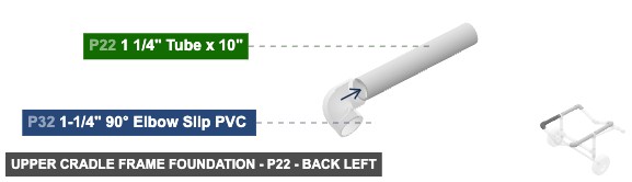
Angle: back left
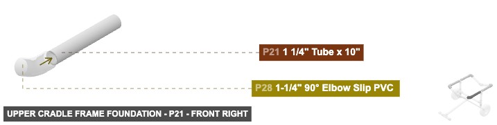
P21 (1.25" Tube 10" length) - attach its 1.25" M SLIP #1 facing front to part 28's 1.25" F SLIP #1. After that, connect its 1.25" M SLIP #2 oriented back links with part 20's 1.25" F SLIP #2
P22 (1.25" Tube 10" length) - its 1.25" M SLIP #1, which is back-facing, should connect to part 32's 1.25" F SLIP #1, also attach its 1.25" M SLIP #2 facing front to part 20's 1.25" F SLIP #1
P23 (1.25" Tube 10" length) - its 1.25" M SLIP #1, which is front-facing, should connect to part 25's 1.25" F SLIP #1, also attach its 1.25" M SLIP #2 facing back to part 19's 1.25" F SLIP #2
P24 (1.25" Tube 10" length) - attach its 1.25" M SLIP #1 facing back to part 29's 1.25" F SLIP #1. Also, attach its 1.25" M SLIP #2 facing front to part 19's 1.25" F SLIP #1
P25 (1.25" 90° Elbow Slip PVC ) - its 1.25" F SLIP #1, which is back-facing, should connect to part 23's 1.25" M SLIP #1, and its 1.25" F SLIP #2, which is right-facing, should connect to part 26's 1.25" M SLIP #2
P28 (1.25" 90° Elbow Slip PVC ) - connect its 1.25" F SLIP #1 oriented back links with part 21's 1.25" M SLIP #1. After that, its 1.25" F SLIP #2, which is left-facing, should connect to part 34's 1.25" M SLIP #1
P29 (1.25" 90° Elbow Slip PVC ) - connect its 1.25" F SLIP #1 oriented front links with part 24's 1.25" M SLIP #1. After that, connect its 1.25" F SLIP #2 oriented right links with part 30's 1.25" M SLIP #2
P32 (1.25" 90° Elbow Slip PVC ) - its 1.25" F SLIP #1, which is front-facing, should connect to part 22's 1.25" M SLIP #1, then its 1.25" F SLIP #2, which is left-facing, should connect to part 33's 1.25" M SLIP #2
1 1/4" Tube x 10"x 4 1-1/4" 90° Elbow Slip PVC x 4
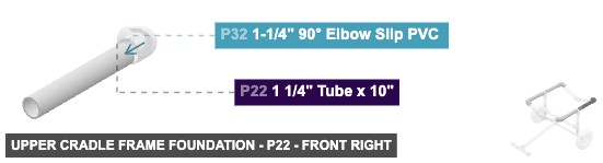
Angle: front right
P21 (1.25" Tube 10" length) - attach its 1.25" M SLIP #1 facing front to part 28's 1.25" F SLIP #1. After that, connect its 1.25" M SLIP #2 oriented back links with part 20's 1.25" F SLIP #2
P22 (1.25" Tube 10" length) - its 1.25" M SLIP #1, which is back-facing, should connect to part 32's 1.25" F SLIP #1, also attach its 1.25" M SLIP #2 facing front to part 20's 1.25" F SLIP #1
P23 (1.25" Tube 10" length) - its 1.25" M SLIP #1, which is front-facing, should connect to part 25's 1.25" F SLIP #1, also attach its 1.25" M SLIP #2 facing back to part 19's 1.25" F SLIP #2
P24 (1.25" Tube 10" length) - attach its 1.25" M SLIP #1 facing back to part 29's 1.25" F SLIP #1. Also, attach its 1.25" M SLIP #2 facing front to part 19's 1.25" F SLIP #1
P25 (1.25" 90° Elbow Slip PVC ) - its 1.25" F SLIP #1, which is back-facing, should connect to part 23's 1.25" M SLIP #1, and its 1.25" F SLIP #2, which is right-facing, should connect to part 26's 1.25" M SLIP #2
P28 (1.25" 90° Elbow Slip PVC ) - connect its 1.25" F SLIP #1 oriented back links with part 21's 1.25" M SLIP #1. After that, its 1.25" F SLIP #2, which is left-facing, should connect to part 34's 1.25" M SLIP #1
P29 (1.25" 90° Elbow Slip PVC ) - connect its 1.25" F SLIP #1 oriented front links with part 24's 1.25" M SLIP #1. After that, connect its 1.25" F SLIP #2 oriented right links with part 30's 1.25" M SLIP #2
P32 (1.25" 90° Elbow Slip PVC ) - its 1.25" F SLIP #1, which is front-facing, should connect to part 22's 1.25" M SLIP #1, then its 1.25" F SLIP #2, which is left-facing, should connect to part 33's 1.25" M SLIP #2
1 1/4" Tube x 10"x 4 1-1/4" 90° Elbow Slip PVC x 4
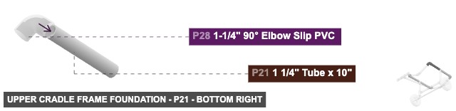
Angle: bottom right
P21 (1.25" Tube 10" length) - attach its 1.25" M SLIP #1 facing front to part 28's 1.25" F SLIP #1. After that, connect its 1.25" M SLIP #2 oriented back links with part 20's 1.25" F SLIP #2
P22 (1.25" Tube 10" length) - its 1.25" M SLIP #1, which is back-facing, should connect to part 32's 1.25" F SLIP #1, also attach its 1.25" M SLIP #2 facing front to part 20's 1.25" F SLIP #1
P23 (1.25" Tube 10" length) - its 1.25" M SLIP #1, which is front-facing, should connect to part 25's 1.25" F SLIP #1, also attach its 1.25" M SLIP #2 facing back to part 19's 1.25" F SLIP #2
P24 (1.25" Tube 10" length) - attach its 1.25" M SLIP #1 facing back to part 29's 1.25" F SLIP #1. Also, attach its 1.25" M SLIP #2 facing front to part 19's 1.25" F SLIP #1
P25 (1.25" 90° Elbow Slip PVC ) - its 1.25" F SLIP #1, which is back-facing, should connect to part 23's 1.25" M SLIP #1, and its 1.25" F SLIP #2, which is right-facing, should connect to part 26's 1.25" M SLIP #2
P28 (1.25" 90° Elbow Slip PVC ) - connect its 1.25" F SLIP #1 oriented back links with part 21's 1.25" M SLIP #1. After that, its 1.25" F SLIP #2, which is left-facing, should connect to part 34's 1.25" M SLIP #1
P29 (1.25" 90° Elbow Slip PVC ) - connect its 1.25" F SLIP #1 oriented front links with part 24's 1.25" M SLIP #1. After that, connect its 1.25" F SLIP #2 oriented right links with part 30's 1.25" M SLIP #2
P32 (1.25" 90° Elbow Slip PVC ) - its 1.25" F SLIP #1, which is front-facing, should connect to part 22's 1.25" M SLIP #1, then its 1.25" F SLIP #2, which is left-facing, should connect to part 33's 1.25" M SLIP #2
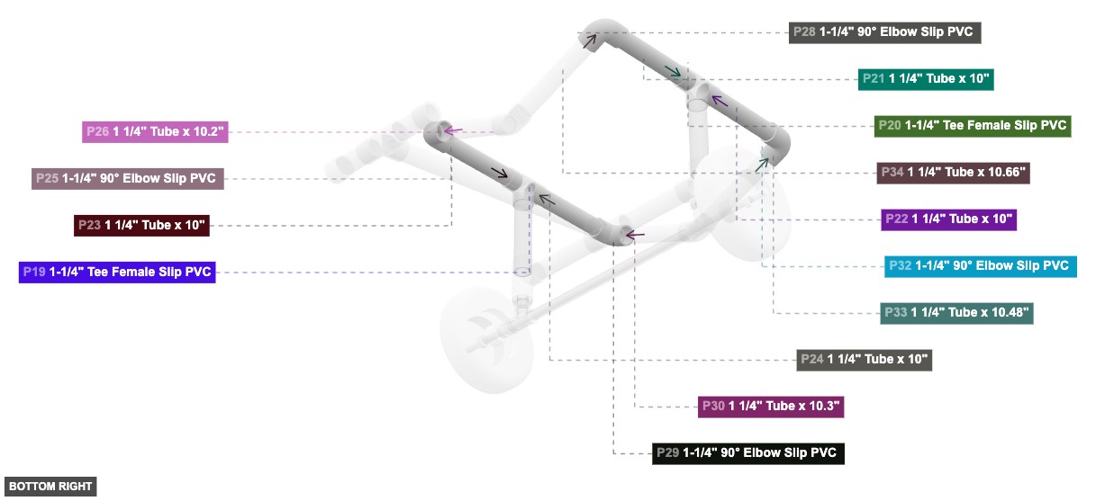
1 1/4" Tube x 10"x 4 1-1/4" 90° Elbow Slip PVC x 4 Attaching: Upper Cradle Completion
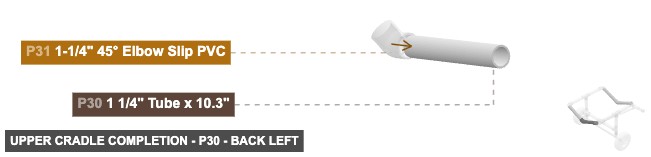
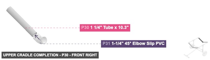
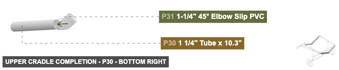
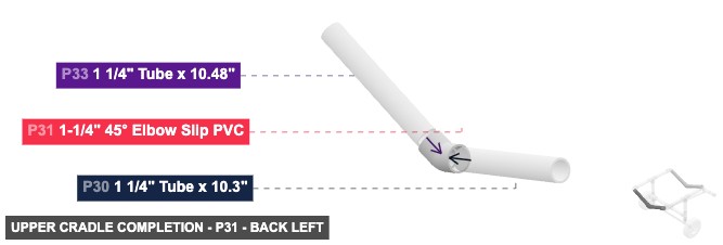
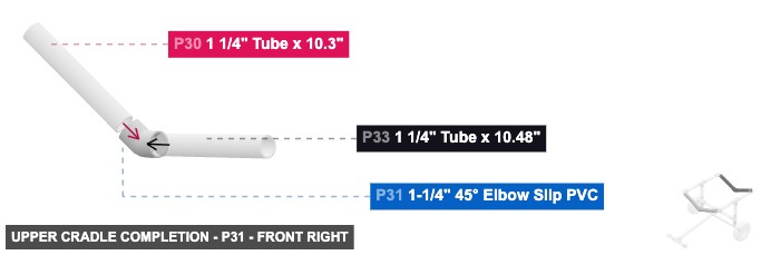
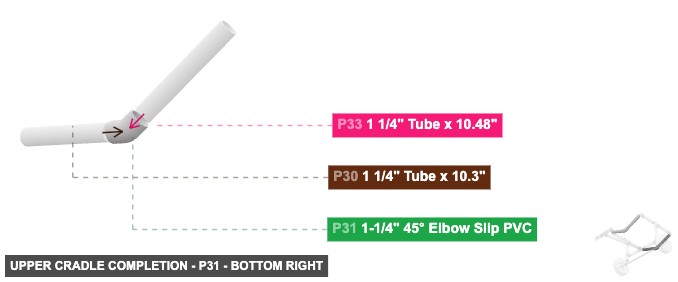
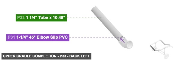
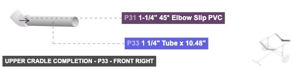
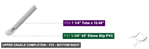
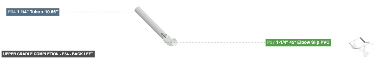
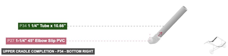
Completes the upper kayak cradle by adding side tubes and angled connectors.
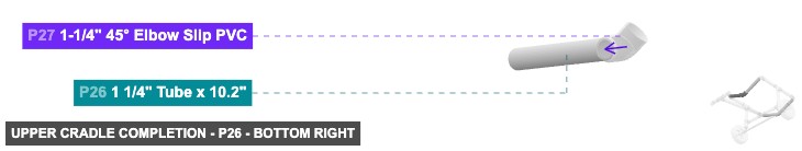
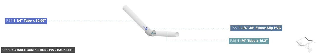
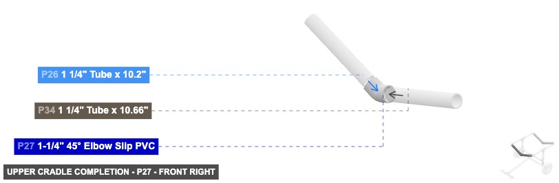
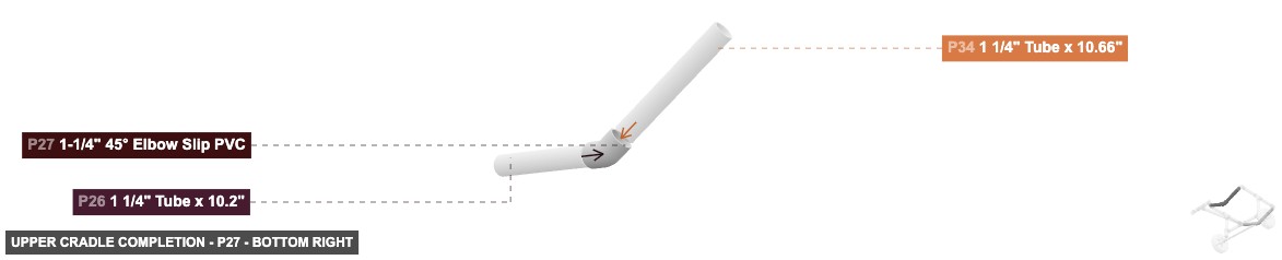
Connect these final tubes and elbows to the open connections on the Upper Cradle Frame Foundation (Group 4) to complete the cart.
Angle: back left
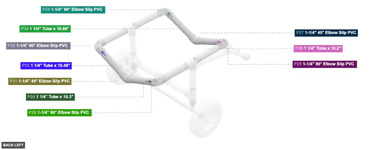
P26 (1.25" Tube 10.2" length) - attach its 1.25" M SLIP #1 facing right to part 27's 1.25" F SLIP #1. Also, attach its 1.25" M SLIP #2 facing left to part 25's 1.25" F SLIP #2
P27 (1.25" 45° Elbow Slip PVC) - connect its 1.25" F SLIP #1 oriented left links with part 26's 1.25" M SLIP #1, also its 1.25" F SLIP #2, which is right-facing, should connect to part 34's 1.25" M SLIP #2
P30 (1.25" Tube 10.3" length) - attach its 1.25" M SLIP #1 facing right to part 31's 1.25" F SLIP #1. Next, its 1.25" M SLIP #2, which is left-facing, should connect to part 29's 1.25" F SLIP #2
P31 (1.25" 45° Elbow Slip PVC) - its 1.25" F SLIP #1, which is left-facing, should connect to part 30's 1.25" M SLIP #1. Also, connect its 1.25" F SLIP #2 oriented right links with part 33's 1.25" M SLIP #1
P33 (1.25" Tube 10.48" length) - connect its 1.25" M SLIP #1 oriented left links with part 31's 1.25" F SLIP #2, then connect its 1.25" M SLIP #2 oriented right links with part 32's 1.25" F SLIP #2
P34 (1.25" Tube 10.66" length) - attach its 1.25" M SLIP #1 facing right to part 28's 1.25" F SLIP #2. After that, connect its 1.25" M SLIP #2 oriented left links with part 27's 1.25" F SLIP #2
1 1/4" Tube x 10.2"x 1 1-1/4" 45° Elbow Slip PVCx 2 1 1/4" Tube x 10.3"x 1 1 1/4" Tube x 10.48"x 1 1 1/4" Tube x 10.66"x 1
Angle: front right
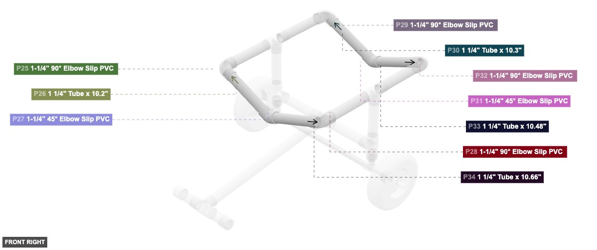
P26 (1.25" Tube 10.2" length) - attach its 1.25" M SLIP #1 facing right to part 27's 1.25" F SLIP #1. Also, attach its 1.25" M SLIP #2 facing left to part 25's 1.25" F SLIP #2
P27 (1.25" 45° Elbow Slip PVC) - connect its 1.25" F SLIP #1 oriented left links with part 26's 1.25" M SLIP #1, also its 1.25" F SLIP #2, which is right-facing, should connect to part 34's 1.25" M SLIP #2
P30 (1.25" Tube 10.3" length) - attach its 1.25" M SLIP #1 facing right to part 31's 1.25" F SLIP #1. Next, its 1.25" M SLIP #2, which is left-facing, should connect to part 29's 1.25" F SLIP #2
P31 (1.25" 45° Elbow Slip PVC) - its 1.25" F SLIP #1, which is left-facing, should connect to part 30's 1.25" M SLIP #1. Also, connect its 1.25" F SLIP #2 oriented right links with part 33's 1.25" M SLIP #1
P33 (1.25" Tube 10.48" length) - connect its 1.25" M SLIP #1 oriented left links with part 31's 1.25" F SLIP #2, then connect its 1.25" M SLIP #2 oriented right links with part 32's 1.25" F SLIP #2
P34 (1.25" Tube 10.66" length) - attach its 1.25" M SLIP #1 facing right to part 28's 1.25" F SLIP #2. After that, connect its 1.25" M SLIP #2 oriented left links with part 27's 1.25" F SLIP #2
1 1/4" Tube x 10.2"x 1 1-1/4" 45° Elbow Slip PVCx 2 1 1/4" Tube x 10.3"x 1 1 1/4" Tube x 10.48"x 1 1 1/4" Tube x 10.66"x 1
Angle: bottom right
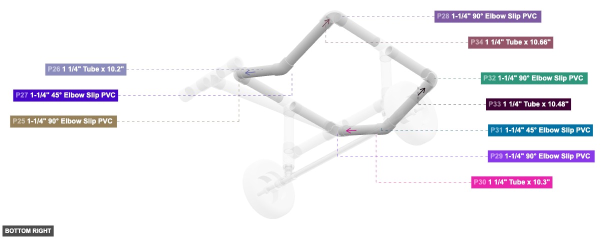
P26 (1.25" Tube 10.2" length) - attach its 1.25" M SLIP #1 facing right to part 27's 1.25" F SLIP #1. Also, attach its 1.25" M SLIP #2 facing left to part 25's 1.25" F SLIP #2
P27 (1.25" 45° Elbow Slip PVC) - connect its 1.25" F SLIP #1 oriented left links with part 26's 1.25" M SLIP #1, also its 1.25" F SLIP #2, which is right-facing, should connect to part 34's 1.25" M SLIP #2
P30 (1.25" Tube 10.3" length) - attach its 1.25" M SLIP #1 facing right to part 31's 1.25" F SLIP #1. Next, its 1.25" M SLIP #2, which is left-facing, should connect to part 29's 1.25" F SLIP #2
P31 (1.25" 45° Elbow Slip PVC) - its 1.25" F SLIP #1, which is left-facing, should connect to part 30's 1.25" M SLIP #1. Also, connect its 1.25" F SLIP #2 oriented right links with part 33's 1.25" M SLIP #1
P33 (1.25" Tube 10.48" length) - connect its 1.25" M SLIP #1 oriented left links with part 31's 1.25" F SLIP #2, then connect its 1.25" M SLIP #2 oriented right links with part 32's 1.25" F SLIP #2
P34 (1.25" Tube 10.66" length) - attach its 1.25" M SLIP #1 facing right to part 28's 1.25" F SLIP #2. After that, connect its 1.25" M SLIP #2 oriented left links with part 27's 1.25" F SLIP #2
1 1/4" Tube x 10.2"x 1 1-1/4" 45° Elbow Slip PVCx 2 1 1/4" Tube x 10.3"x 1 1 1/4" Tube x 10.48"x 1 1 1/4" Tube x 10.66"x 1