Air Rocket Launcher - Comprehensive Assembly Plan And Visual Guide
A PVC-based air rocket launcher featuring an air chamber, a solenoid valve for triggering, a stand, and a launch tube. It appears designed to be pressurized via a tank valve. - Air Rocket Launcher
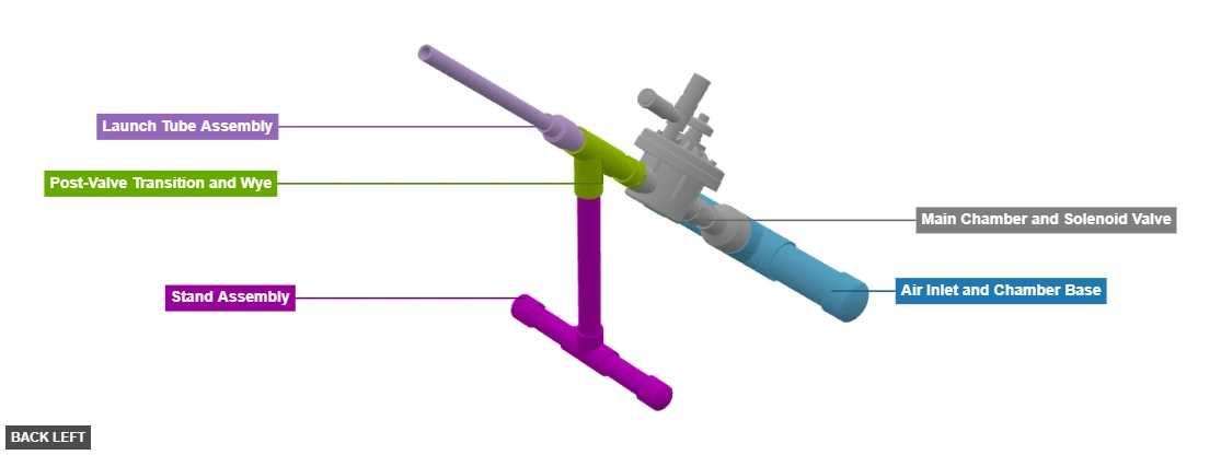
Phase 1: Group Overview
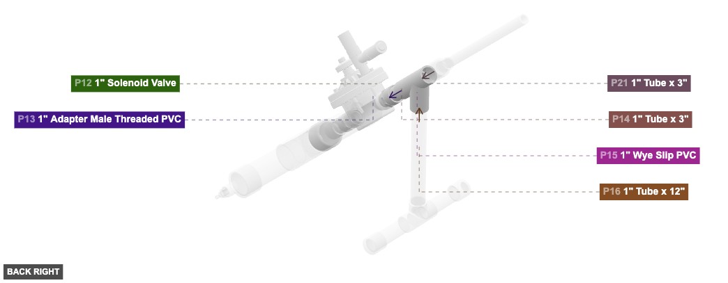
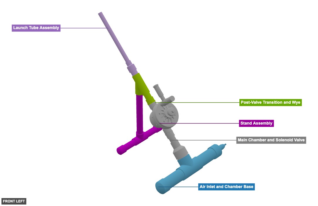
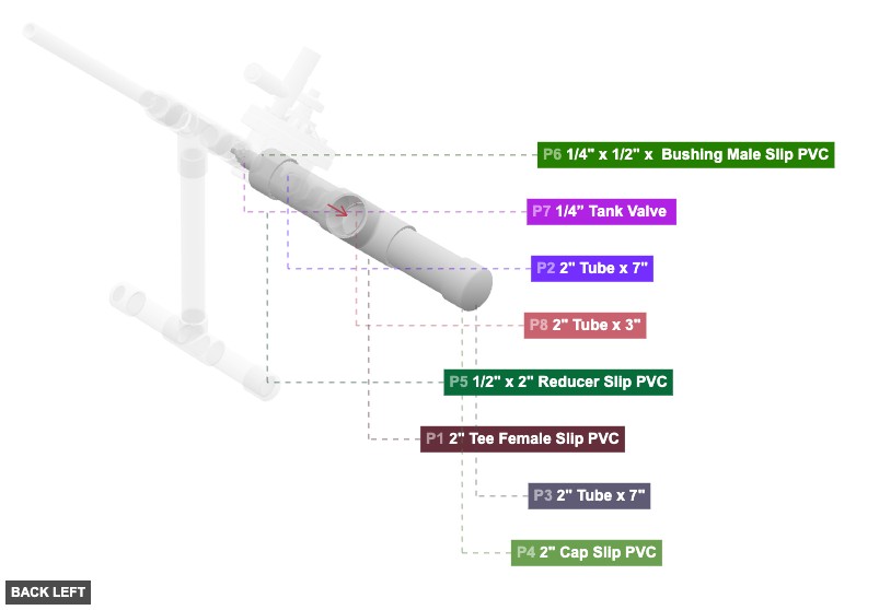
Angle: back left
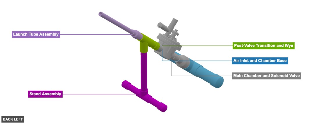
Air Inlet and Chamber Base
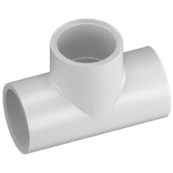 2" Tee Female Slip PVCx 1
 2" Tube x 7"x 2
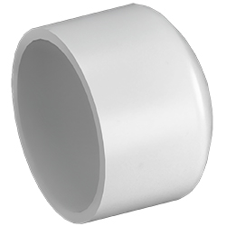 2" Cap Slip PVCx 1
 1/2" x 2" Reducer Slip PVCx 1
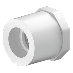 1/4" x 1/2" x Bushing Male Slip PVCx 1
 1/4” Tank Valve x 1
Main Chamber and Solenoid Valve
2" Tube x 3"x 1 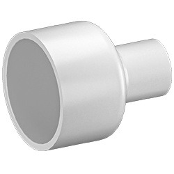 1" x 2" Reducer Slip PVCx 1
 1" Tube x 3"x 1
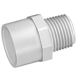 1" Adapter Male Threaded PVCx 1
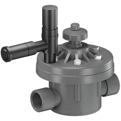 1" Solenoid Valvex 1
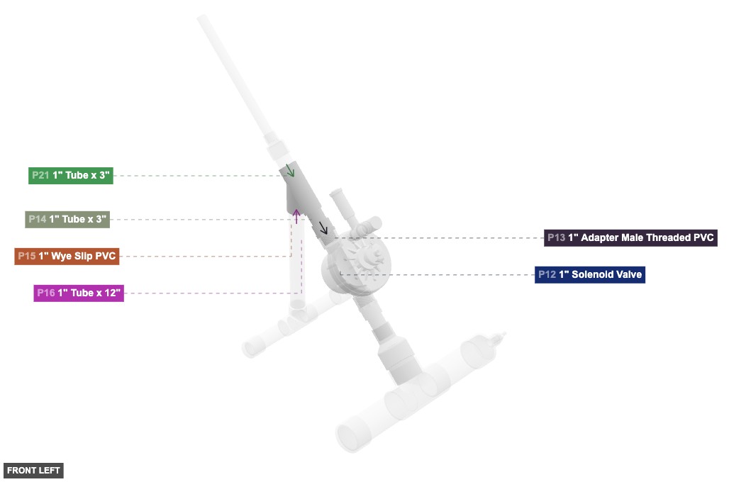
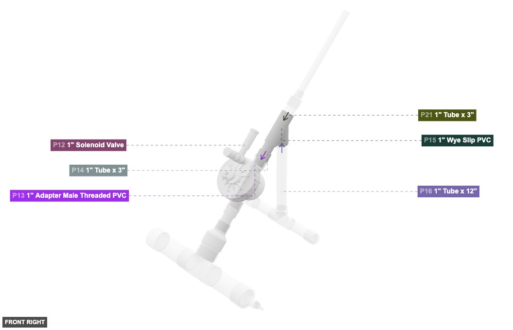
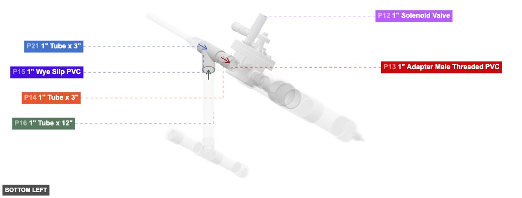
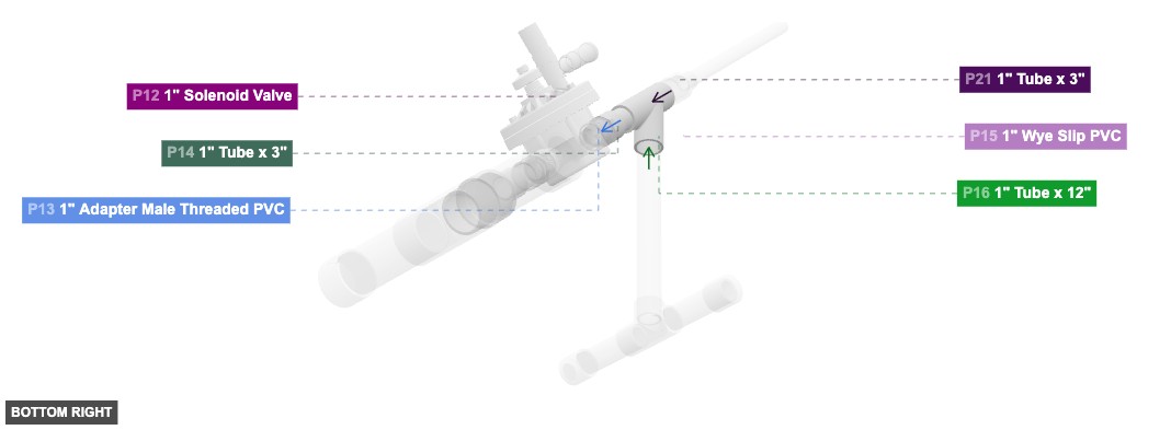
Post-Valve Transition and Wye
1" Adapter Male Threaded PVCx 1 1" Tube x 3"x 1 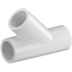 1" Wye Slip PVCx 1
Stand Assembly
1" Tube x 12"x 1  1" Tee Female Slip PVCx 1
1" Tube x 5"x 2  1" Cap Slip PVCx 2
Launch Tube Assembly
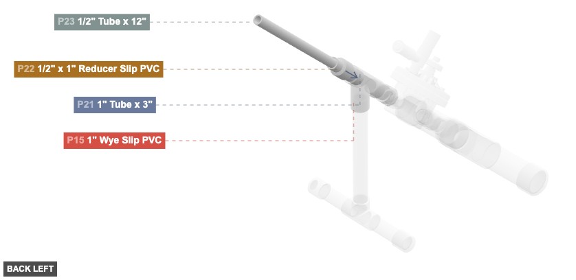
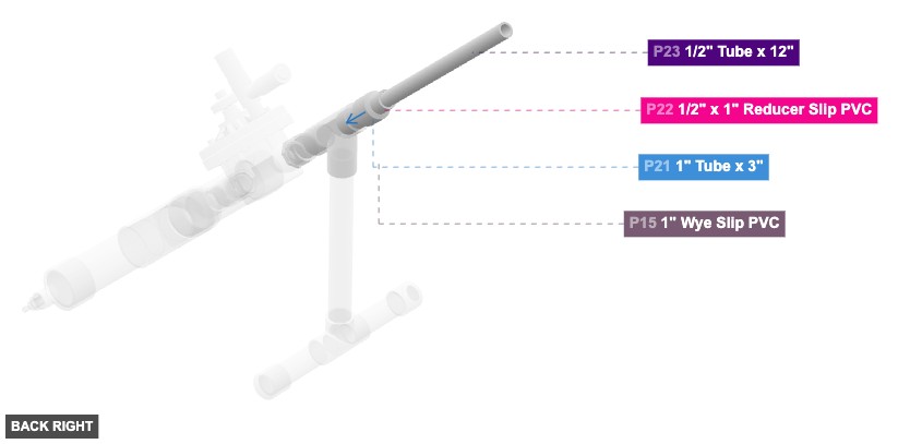
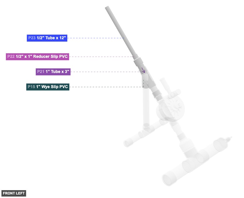
1" Tube x 3"x 1  1/2" x 1" Reducer Slip PVCx 1
 1/2" Tube x 12"x 1
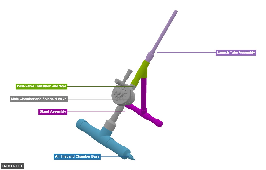
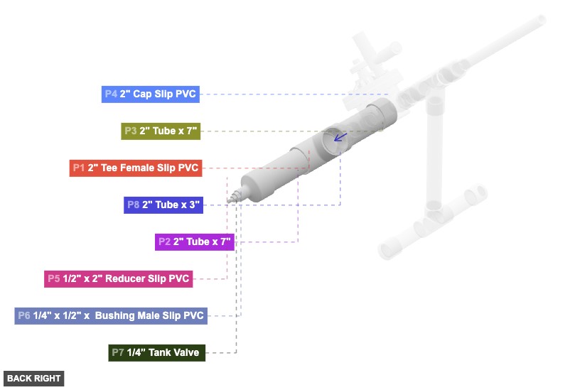
Angle: back right
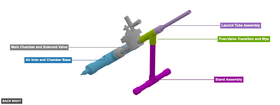
Air Inlet and Chamber Base
2" Tee Female Slip PVCx 1 2" Tube x 7"x 2 2" Cap Slip PVCx 1 1/2" x 2" Reducer Slip PVCx 1 1/4" x 1/2" x Bushing Male Slip PVCx 1 1/4” Tank Valve x 1 Main Chamber and Solenoid Valve
2" Tube x 3"x 1 1" x 2" Reducer Slip PVCx 1 1" Tube x 3"x 1 1" Adapter Male Threaded PVCx 1 1" Solenoid Valvex 1 Post-Valve Transition and Wye
1" Adapter Male Threaded PVCx 1 1" Tube x 3"x 1 1" Wye Slip PVCx 1 Stand Assembly
1" Tube x 12"x 1 1" Tee Female Slip PVCx 1 1" Tube x 5"x 2 1" Cap Slip PVCx 2 Launch Tube Assembly
1" Tube x 3"x 1 1/2" x 1" Reducer Slip PVCx 1 1/2" Tube x 12"x 1
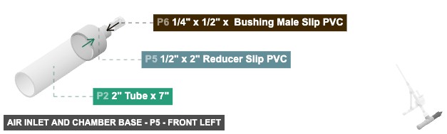
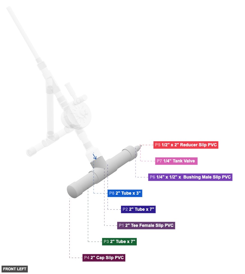
Angle: front left
Air Inlet and Chamber Base
2" Tee Female Slip PVCx 1 2" Tube x 7"x 2 2" Cap Slip PVCx 1 1/2" x 2" Reducer Slip PVCx 1 1/4" x 1/2" x Bushing Male Slip PVCx 1 1/4” Tank Valve x 1 Main Chamber and Solenoid Valve
2" Tube x 3"x 1 1" x 2" Reducer Slip PVCx 1 1" Tube x 3"x 1 1" Adapter Male Threaded PVCx 1 1" Solenoid Valvex 1 Post-Valve Transition and Wye
1" Adapter Male Threaded PVCx 1 1" Tube x 3"x 1 1" Wye Slip PVCx 1 Stand Assembly
1" Tube x 12"x 1 1" Tee Female Slip PVCx 1 1" Tube x 5"x 2 1" Cap Slip PVCx 2 Launch Tube Assembly
1" Tube x 3"x 1 1/2" x 1" Reducer Slip PVCx 1 1/2" Tube x 12"x 1
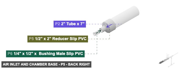
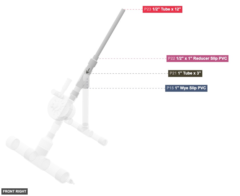
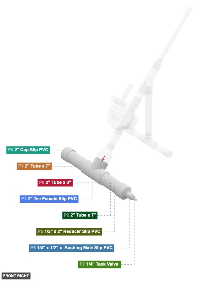
Angle: front right
Air Inlet and Chamber Base
2" Tee Female Slip PVCx 1 2" Tube x 7"x 2 2" Cap Slip PVCx 1 1/2" x 2" Reducer Slip PVCx 1 1/4" x 1/2" x Bushing Male Slip PVCx 1 1/4” Tank Valve x 1 Main Chamber and Solenoid Valve
2" Tube x 3"x 1 1" x 2" Reducer Slip PVCx 1 1" Tube x 3"x 1 1" Adapter Male Threaded PVCx 1 1" Solenoid Valvex 1 Post-Valve Transition and Wye
1" Adapter Male Threaded PVCx 1 1" Tube x 3"x 1 1" Wye Slip PVCx 1 Stand Assembly
1" Tube x 12"x 1 1" Tee Female Slip PVCx 1 1" Tube x 5"x 2 1" Cap Slip PVCx 2 Launch Tube Assembly
1" Tube x 3"x 1 1/2" x 1" Reducer Slip PVCx 1 1/2" Tube x 12"x 1
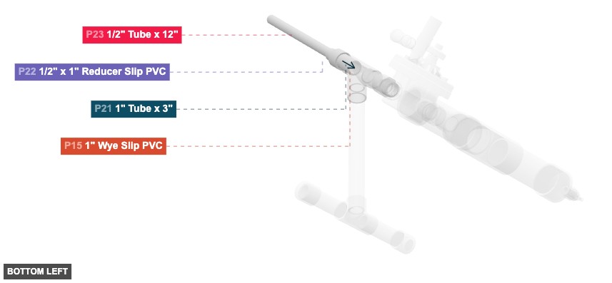
Angle: bottom left
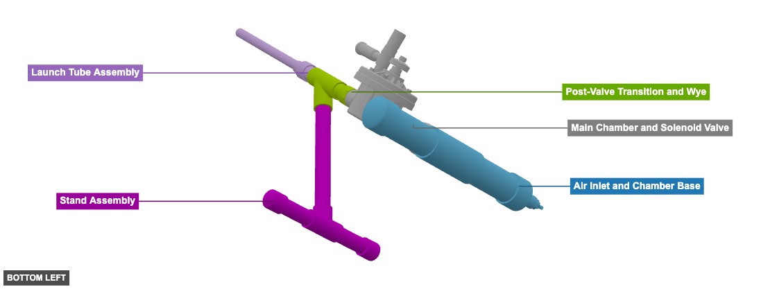
Air Inlet and Chamber Base
2" Tee Female Slip PVCx 1 2" Tube x 7"x 2 2" Cap Slip PVCx 1 1/2" x 2" Reducer Slip PVCx 1 1/4" x 1/2" x Bushing Male Slip PVCx 1 1/4” Tank Valve x 1 Main Chamber and Solenoid Valve
2" Tube x 3"x 1 1" x 2" Reducer Slip PVCx 1 1" Tube x 3"x 1 1" Adapter Male Threaded PVCx 1 1" Solenoid Valvex 1 Post-Valve Transition and Wye
1" Adapter Male Threaded PVCx 1 1" Tube x 3"x 1 1" Wye Slip PVCx 1 Stand Assembly
1" Tube x 12"x 1 1" Tee Female Slip PVCx 1 1" Tube x 5"x 2 1" Cap Slip PVCx 2 Launch Tube Assembly
1" Tube x 3"x 1 1/2" x 1" Reducer Slip PVCx 1 1/2" Tube x 12"x 1
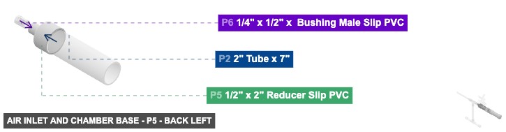
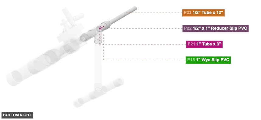
Angle: bottom right
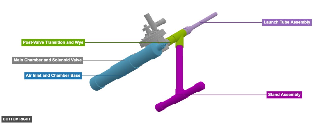
Air Inlet and Chamber Base
2" Tee Female Slip PVCx 1 2" Tube x 7"x 2 2" Cap Slip PVCx 1 1/2" x 2" Reducer Slip PVCx 1 1/4" x 1/2" x Bushing Male Slip PVCx 1 1/4” Tank Valve x 1 Main Chamber and Solenoid Valve
2" Tube x 3"x 1 1" x 2" Reducer Slip PVCx 1 1" Tube x 3"x 1 1" Adapter Male Threaded PVCx 1 1" Solenoid Valvex 1 Post-Valve Transition and Wye
1" Adapter Male Threaded PVCx 1 1" Tube x 3"x 1 1" Wye Slip PVCx 1 Stand Assembly
1" Tube x 12"x 1 1" Tee Female Slip PVCx 1 1" Tube x 5"x 2 1" Cap Slip PVCx 2 Launch Tube Assembly
1" Tube x 3"x 1 1/2" x 1" Reducer Slip PVCx 1 1/2" Tube x 12"x 1 Phase 2: Individual Group Assembly
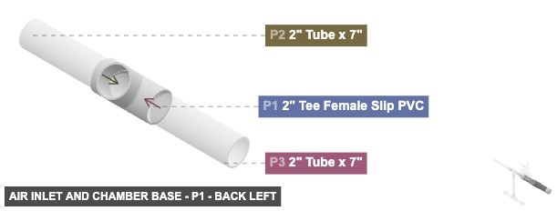
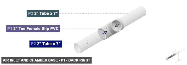
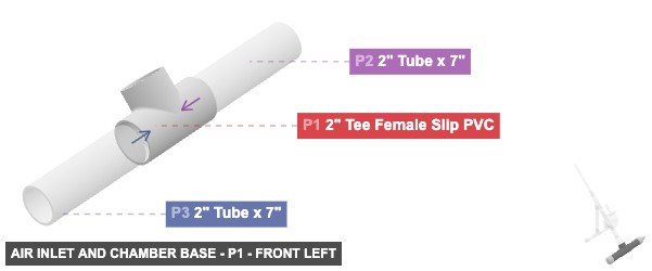
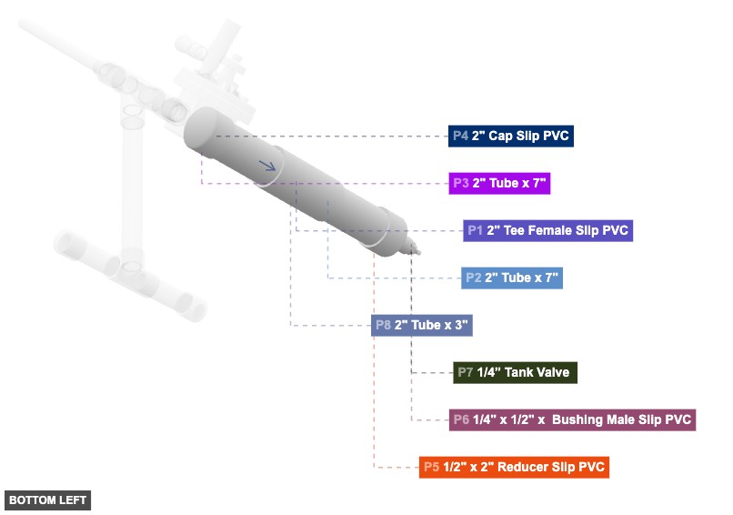
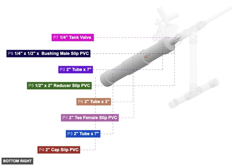
Group: Air Inlet and Chamber Base
Forms the initial air chamber section, including the air inlet valve connection point.
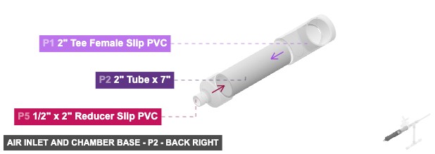
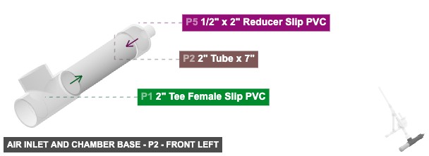
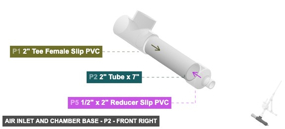
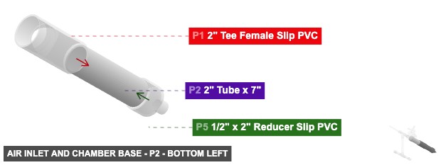
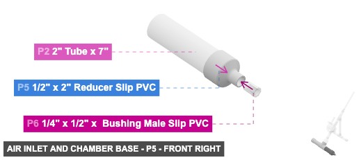
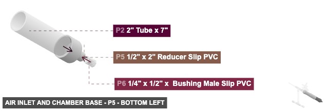
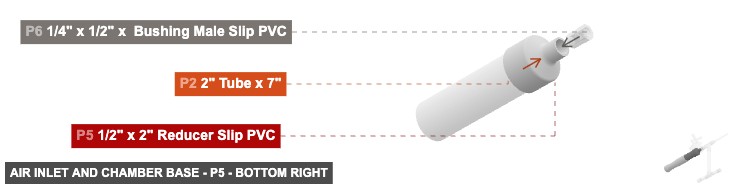
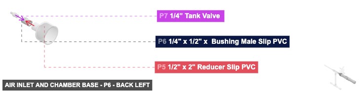
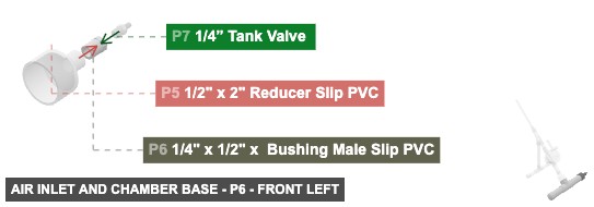
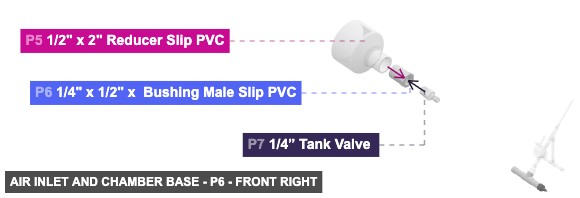
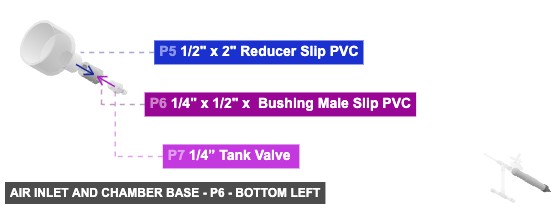
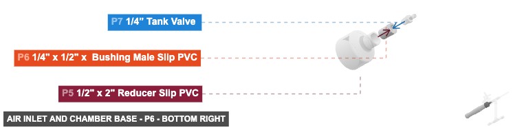
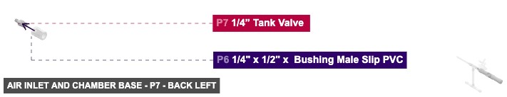
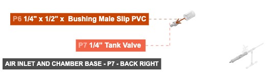
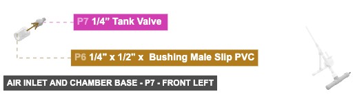
Connect P2 (2" Tube 7") Male SLIP into the right-facing P1 (2" Tee) Female SLIP. Connect P3 (2" Tube 7") Male SLIP into the left-facing P1 (2" Tee) Female SLIP. Attach P4 (2" Cap) Female SLIP onto the open end of P3. Attach P5 (1/2" x 2" Reducer) 2" Female SLIP onto the open end of P2. Connect P6 (1/4" x 1/2" Bushing) 1/2" Male SLIP into the P5 (1/2" x 2" Reducer) 1/2" Female SLIP. Thread P7 (1/4" Tank Valve) Male Threaded into the P6 (1/4" x 1/2" Bushing) 1/4" Female Threaded.
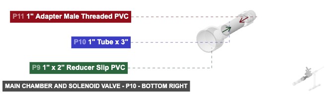
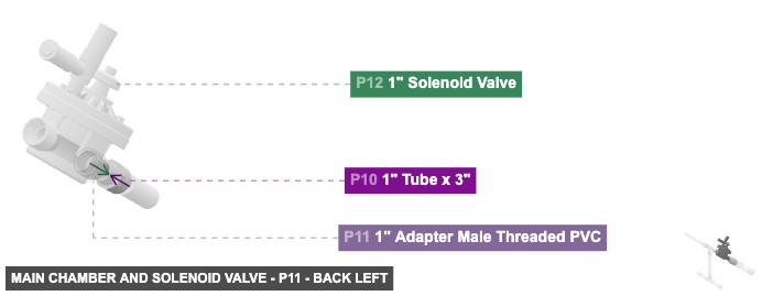
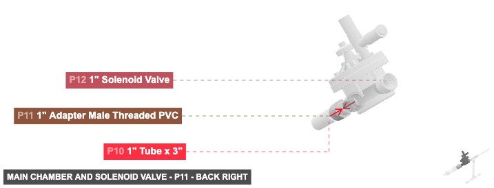
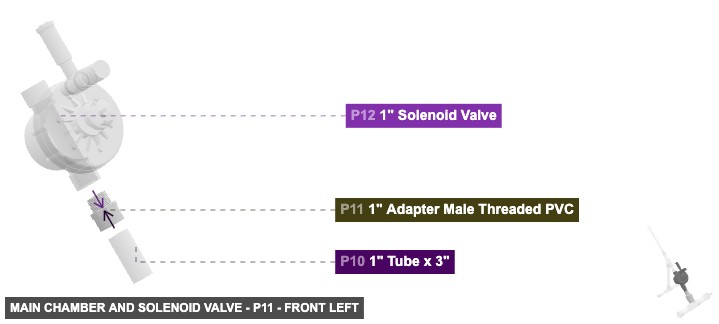
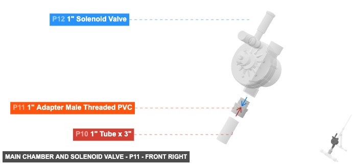
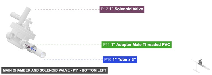
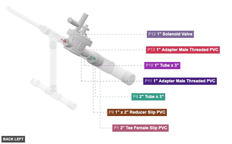
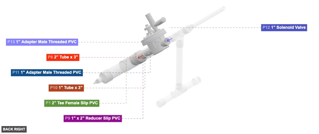
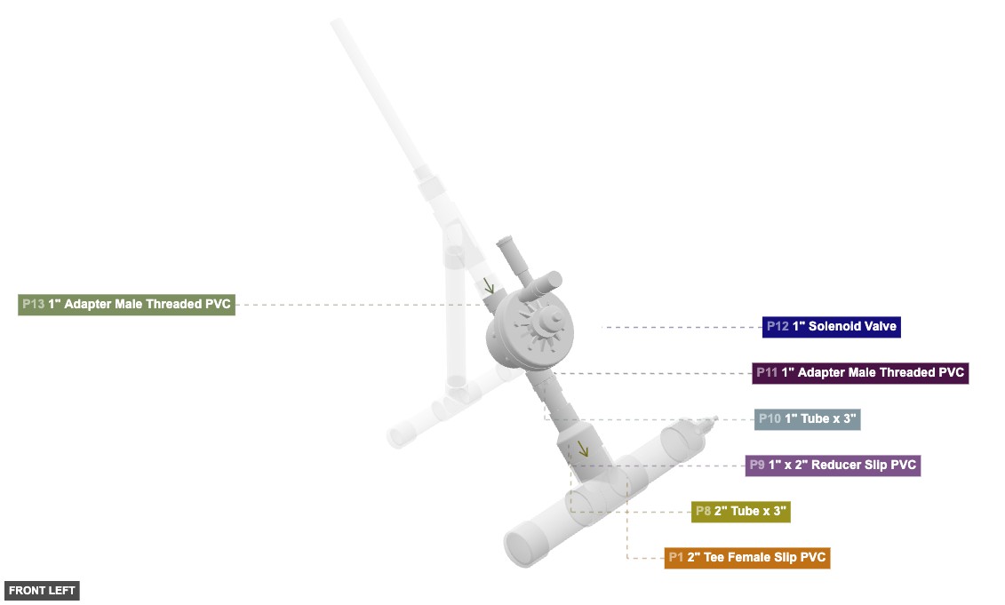
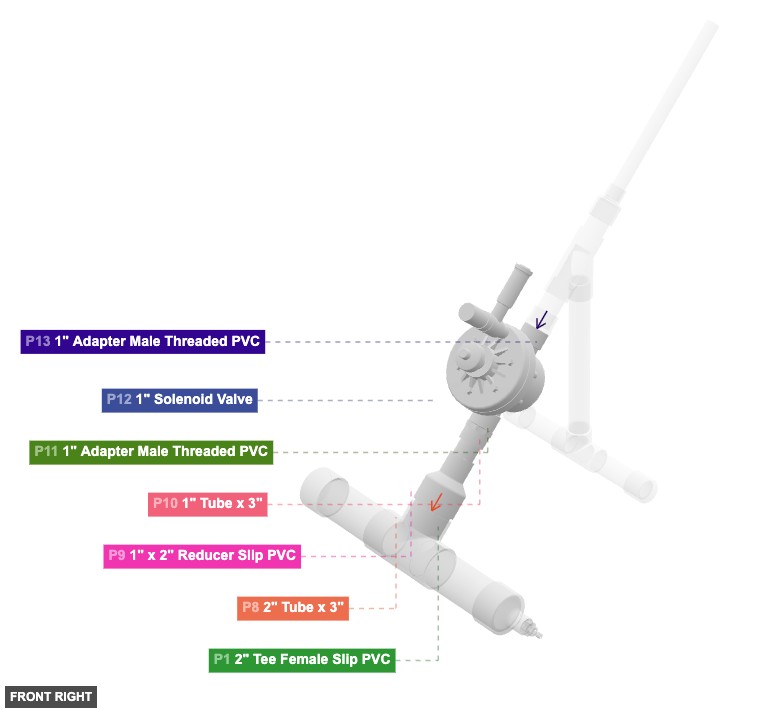
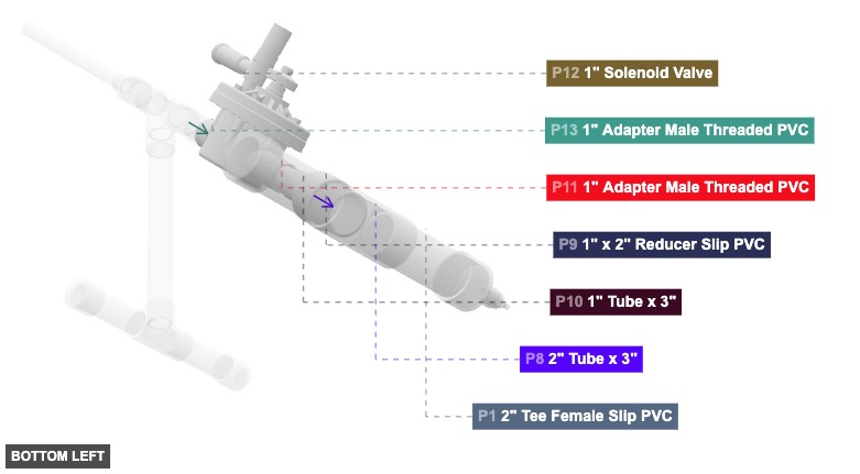
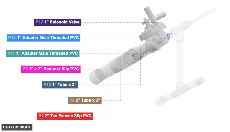
Group: Main Chamber and Solenoid Valve
Constructs the main vertical air chamber leading up to and including the electronic solenoid valve.
Connect P8 (2" Tube 3") Male SLIP into the P9 (1" x 2" Reducer) 2" Female SLIP. Connect P10 (1" Tube 3") Male SLIP into the P9 (1" x 2" Reducer) 1" Female SLIP. Connect P11 (1" Adapter Male Threaded) 1" Female SLIP onto the open end of P10. Thread the P12 (1" Solenoid Valve) bottom 1" Female Threaded onto the P11 (1" Adapter Male Threaded) 1" Male Threaded.
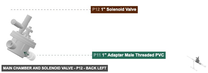
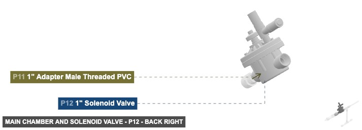
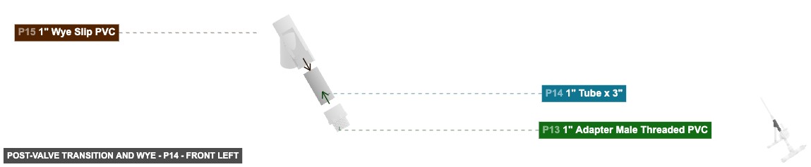
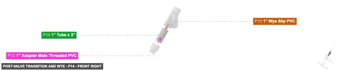
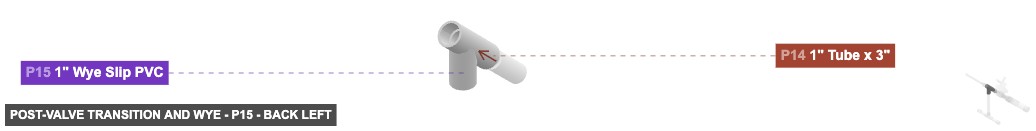
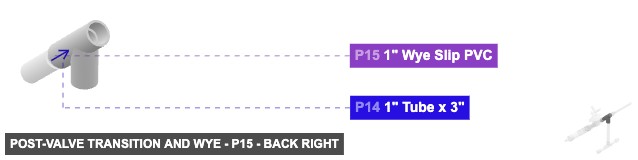
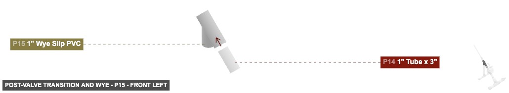
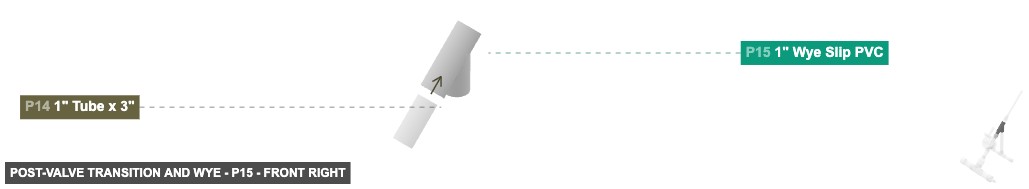
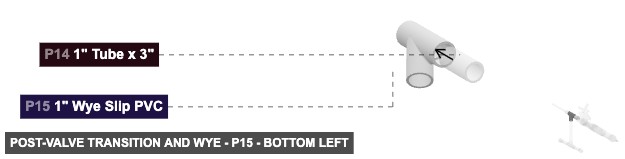
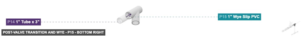
Group: Post-Valve Transition and Wye
Connects the solenoid valve output, splitting the path towards the launch tube and the stand using a Wye fitting.
Thread P13 (1" Adapter Male Threaded) 1" Male Threaded into the top P12 (1" Solenoid Valve) 1" Female Threaded. Connect P14 (1" Tube 3") Male SLIP into the P13 (1" Adapter Male Threaded) 1" Female SLIP. Connect the P15 (1" Wye) front-bottom 1" Female SLIP onto the open end of P14.
Group: Stand Assembly
Creates the T-shaped base stand for the launcher.
Connect P16 (1" Tube 12") Male SLIP into the top P17 (1" Tee) 1" Female SLIP. Connect P18 (1" Tube 5") Male SLIP into the left P17 (1" Tee) 1" Female SLIP. Connect P24 (1" Tube 5") Male SLIP into the right P17 (1" Tee) 1" Female SLIP. Attach P20 (1" Cap) 1" Female SLIP onto the open end of P18. Attach P19 (1" Cap) 1" Female SLIP onto the open end of P24.
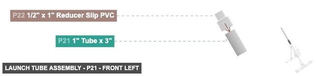
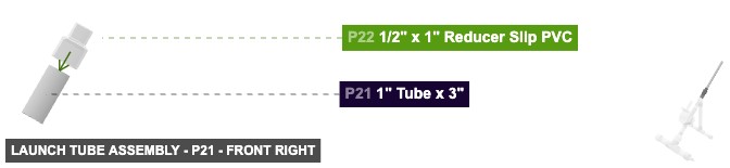
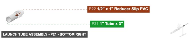
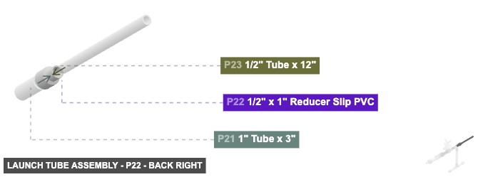
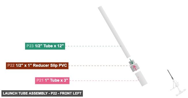
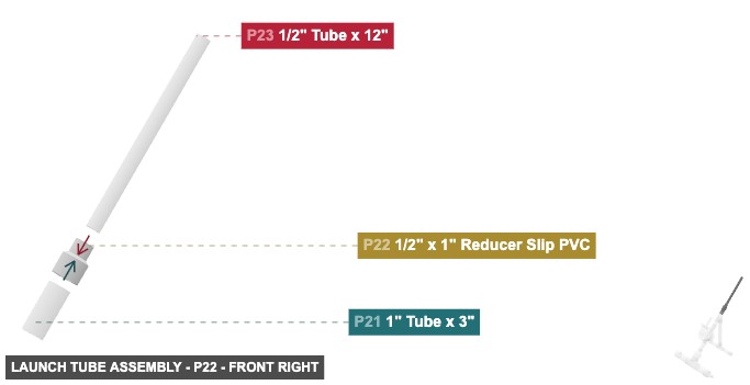
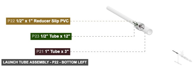
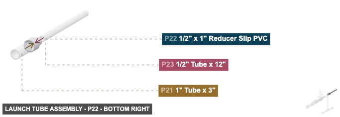
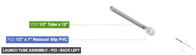
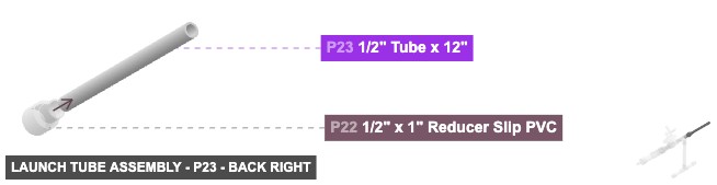
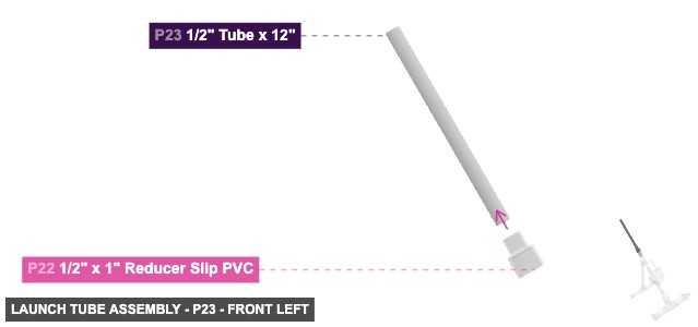
Group: Launch Tube Assembly
Forms the final launch tube where the rocket is placed.
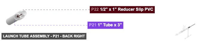
Connect P21 (1" Tube 3") Male SLIP into the P22 (1/2" x 1" Reducer) 1" Female SLIP. Connect P23 (1/2" Tube 12") Male SLIP into the P22 (1/2" x 1" Reducer) 1/2" Female SLIP.
Phase 3: Inter-Group Assembly
Attaching: Air Inlet and Chamber Base
Forms the initial air chamber section, including the air inlet valve connection point.
Connect the top-facing 2" Female SLIP of P1 to the Main Chamber Assembly (starting with P8).
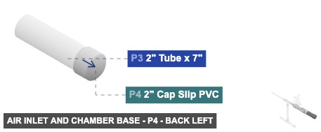
Angle: back left
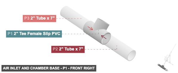
P1 (2" Tee F Slip PVC) - connect its 2" F SLIP #1 oriented right links with part 2's 2" M SLIP #2, and its 2" F SLIP #2, which is left-facing, should connect to part 3's 2" M SLIP #2, plus its 2" F SLIP #3, which is back-top-facing, should connect to part 8's 2" M SLIP #2
P2 (2" Tube 7" length) - connect its 2" M SLIP #1 oriented right links with part 5's 2" F SLIP #1. Next, attach its 2" M SLIP #2 facing left to part 1's 2" F SLIP #1
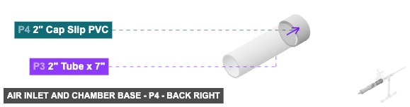
P3 (2" Tube 7" length) - its 2" M SLIP #1, which is left-facing, should connect to part 4's 2" F SLIP #1. After that, connect its 2" M SLIP #2 oriented right links with part 1's 2" F SLIP #2
P4 (2" Cap Slip PVC) - its 2" F SLIP #1, which is right-facing, should connect to part 3's 2" M SLIP #1
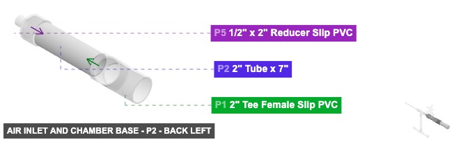
P5 (0.5" x 2" Reducer Slip PVC) - its 0.5" F SLIP #1, which is right-facing, should connect to part 6's 0.5" M SLIP #1, and its 2" F SLIP #1, which is left-facing, should connect to part 2's 2" M SLIP #1
P6 (0.25" x 1/2" x Bushing M Slip PVC) - its 0.25" F Threaded #1, which is right-facing, should connect to part 7's 0.25" M Threaded #1, then attach its 0.5" M SLIP #1 facing left to part 5's 0.5" F SLIP #1
P7 (0.25"” Tank Valve ) - attach its 0.25" M Threaded #1 facing left to part 6's 0.25" F Threaded #1
2" Tee Female Slip PVCx 1 2" Tube x 7"x 2 2" Cap Slip PVCx 1 1/2" x 2" Reducer Slip PVCx 1 1/4" x 1/2" x Bushing Male Slip PVCx 1 1/4” Tank Valve x 1
Angle: back right
P1 (2" Tee F Slip PVC) - connect its 2" F SLIP #1 oriented right links with part 2's 2" M SLIP #2, and its 2" F SLIP #2, which is left-facing, should connect to part 3's 2" M SLIP #2, plus its 2" F SLIP #3, which is back-top-facing, should connect to part 8's 2" M SLIP #2
P2 (2" Tube 7" length) - connect its 2" M SLIP #1 oriented right links with part 5's 2" F SLIP #1. Next, attach its 2" M SLIP #2 facing left to part 1's 2" F SLIP #1
P3 (2" Tube 7" length) - its 2" M SLIP #1, which is left-facing, should connect to part 4's 2" F SLIP #1. After that, connect its 2" M SLIP #2 oriented right links with part 1's 2" F SLIP #2
P4 (2" Cap Slip PVC) - its 2" F SLIP #1, which is right-facing, should connect to part 3's 2" M SLIP #1
P5 (0.5" x 2" Reducer Slip PVC) - its 0.5" F SLIP #1, which is right-facing, should connect to part 6's 0.5" M SLIP #1, and its 2" F SLIP #1, which is left-facing, should connect to part 2's 2" M SLIP #1
P6 (0.25" x 1/2" x Bushing M Slip PVC) - its 0.25" F Threaded #1, which is right-facing, should connect to part 7's 0.25" M Threaded #1, then attach its 0.5" M SLIP #1 facing left to part 5's 0.5" F SLIP #1
P7 (0.25"” Tank Valve ) - attach its 0.25" M Threaded #1 facing left to part 6's 0.25" F Threaded #1
2" Tee Female Slip PVCx 1 2" Tube x 7"x 2 2" Cap Slip PVCx 1 1/2" x 2" Reducer Slip PVCx 1 1/4" x 1/2" x Bushing Male Slip PVCx 1 1/4” Tank Valve x 1
Angle: front left
P1 (2" Tee F Slip PVC) - connect its 2" F SLIP #1 oriented right links with part 2's 2" M SLIP #2, and its 2" F SLIP #2, which is left-facing, should connect to part 3's 2" M SLIP #2, plus its 2" F SLIP #3, which is back-top-facing, should connect to part 8's 2" M SLIP #2
P2 (2" Tube 7" length) - connect its 2" M SLIP #1 oriented right links with part 5's 2" F SLIP #1. Next, attach its 2" M SLIP #2 facing left to part 1's 2" F SLIP #1
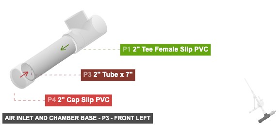
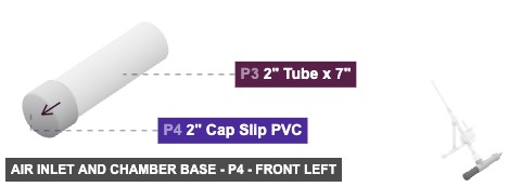
P3 (2" Tube 7" length) - its 2" M SLIP #1, which is left-facing, should connect to part 4's 2" F SLIP #1. After that, connect its 2" M SLIP #2 oriented right links with part 1's 2" F SLIP #2
P4 (2" Cap Slip PVC) - its 2" F SLIP #1, which is right-facing, should connect to part 3's 2" M SLIP #1
P5 (0.5" x 2" Reducer Slip PVC) - its 0.5" F SLIP #1, which is right-facing, should connect to part 6's 0.5" M SLIP #1, and its 2" F SLIP #1, which is left-facing, should connect to part 2's 2" M SLIP #1
P6 (0.25" x 1/2" x Bushing M Slip PVC) - its 0.25" F Threaded #1, which is right-facing, should connect to part 7's 0.25" M Threaded #1, then attach its 0.5" M SLIP #1 facing left to part 5's 0.5" F SLIP #1
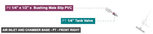
P7 (0.25"” Tank Valve ) - attach its 0.25" M Threaded #1 facing left to part 6's 0.25" F Threaded #1
2" Tee Female Slip PVCx 1 2" Tube x 7"x 2 2" Cap Slip PVCx 1 1/2" x 2" Reducer Slip PVCx 1 1/4" x 1/2" x Bushing Male Slip PVCx 1 1/4” Tank Valve x 1
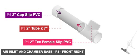
Angle: front right
P1 (2" Tee F Slip PVC) - connect its 2" F SLIP #1 oriented right links with part 2's 2" M SLIP #2, and its 2" F SLIP #2, which is left-facing, should connect to part 3's 2" M SLIP #2, plus its 2" F SLIP #3, which is back-top-facing, should connect to part 8's 2" M SLIP #2
P2 (2" Tube 7" length) - connect its 2" M SLIP #1 oriented right links with part 5's 2" F SLIP #1. Next, attach its 2" M SLIP #2 facing left to part 1's 2" F SLIP #1
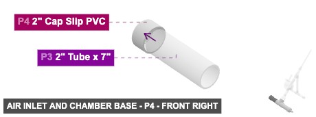
P3 (2" Tube 7" length) - its 2" M SLIP #1, which is left-facing, should connect to part 4's 2" F SLIP #1. After that, connect its 2" M SLIP #2 oriented right links with part 1's 2" F SLIP #2
P4 (2" Cap Slip PVC) - its 2" F SLIP #1, which is right-facing, should connect to part 3's 2" M SLIP #1
P5 (0.5" x 2" Reducer Slip PVC) - its 0.5" F SLIP #1, which is right-facing, should connect to part 6's 0.5" M SLIP #1, and its 2" F SLIP #1, which is left-facing, should connect to part 2's 2" M SLIP #1
P6 (0.25" x 1/2" x Bushing M Slip PVC) - its 0.25" F Threaded #1, which is right-facing, should connect to part 7's 0.25" M Threaded #1, then attach its 0.5" M SLIP #1 facing left to part 5's 0.5" F SLIP #1
P7 (0.25"” Tank Valve ) - attach its 0.25" M Threaded #1 facing left to part 6's 0.25" F Threaded #1
2" Tee Female Slip PVCx 1 2" Tube x 7"x 2 2" Cap Slip PVCx 1 1/2" x 2" Reducer Slip PVCx 1 1/4" x 1/2" x Bushing Male Slip PVCx 1 1/4” Tank Valve x 1
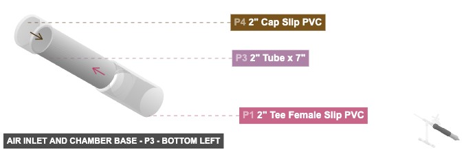
Angle: bottom left
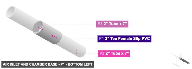
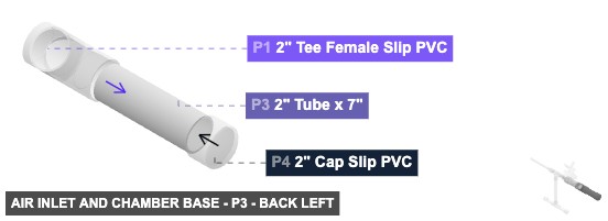
P1 (2" Tee F Slip PVC) - connect its 2" F SLIP #1 oriented right links with part 2's 2" M SLIP #2, and its 2" F SLIP #2, which is left-facing, should connect to part 3's 2" M SLIP #2, plus its 2" F SLIP #3, which is back-top-facing, should connect to part 8's 2" M SLIP #2
P2 (2" Tube 7" length) - connect its 2" M SLIP #1 oriented right links with part 5's 2" F SLIP #1. Next, attach its 2" M SLIP #2 facing left to part 1's 2" F SLIP #1
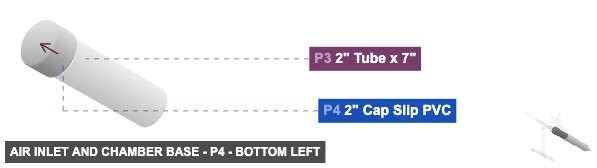
P3 (2" Tube 7" length) - its 2" M SLIP #1, which is left-facing, should connect to part 4's 2" F SLIP #1. After that, connect its 2" M SLIP #2 oriented right links with part 1's 2" F SLIP #2
P4 (2" Cap Slip PVC) - its 2" F SLIP #1, which is right-facing, should connect to part 3's 2" M SLIP #1
P5 (0.5" x 2" Reducer Slip PVC) - its 0.5" F SLIP #1, which is right-facing, should connect to part 6's 0.5" M SLIP #1, and its 2" F SLIP #1, which is left-facing, should connect to part 2's 2" M SLIP #1
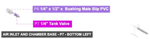
P6 (0.25" x 1/2" x Bushing M Slip PVC) - its 0.25" F Threaded #1, which is right-facing, should connect to part 7's 0.25" M Threaded #1, then attach its 0.5" M SLIP #1 facing left to part 5's 0.5" F SLIP #1
P7 (0.25"” Tank Valve ) - attach its 0.25" M Threaded #1 facing left to part 6's 0.25" F Threaded #1
2" Tee Female Slip PVCx 1 2" Tube x 7"x 2 2" Cap Slip PVCx 1 1/2" x 2" Reducer Slip PVCx 1 1/4" x 1/2" x Bushing Male Slip PVCx 1 1/4” Tank Valve x 1
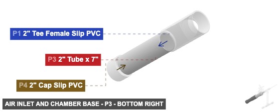
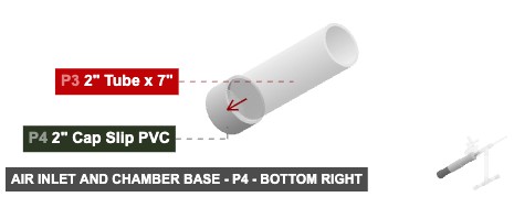
Angle: bottom right
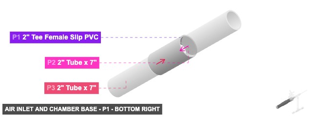
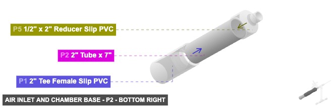
P1 (2" Tee F Slip PVC) - connect its 2" F SLIP #1 oriented right links with part 2's 2" M SLIP #2, and its 2" F SLIP #2, which is left-facing, should connect to part 3's 2" M SLIP #2, plus its 2" F SLIP #3, which is back-top-facing, should connect to part 8's 2" M SLIP #2
P2 (2" Tube 7" length) - connect its 2" M SLIP #1 oriented right links with part 5's 2" F SLIP #1. Next, attach its 2" M SLIP #2 facing left to part 1's 2" F SLIP #1
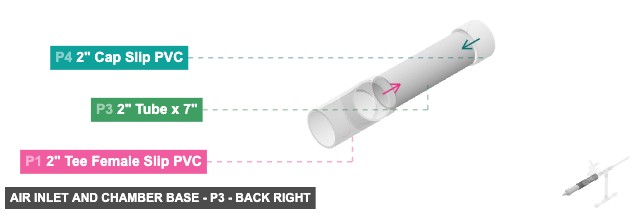
P3 (2" Tube 7" length) - its 2" M SLIP #1, which is left-facing, should connect to part 4's 2" F SLIP #1. After that, connect its 2" M SLIP #2 oriented right links with part 1's 2" F SLIP #2
P4 (2" Cap Slip PVC) - its 2" F SLIP #1, which is right-facing, should connect to part 3's 2" M SLIP #1
P5 (0.5" x 2" Reducer Slip PVC) - its 0.5" F SLIP #1, which is right-facing, should connect to part 6's 0.5" M SLIP #1, and its 2" F SLIP #1, which is left-facing, should connect to part 2's 2" M SLIP #1
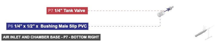
P6 (0.25" x 1/2" x Bushing M Slip PVC) - its 0.25" F Threaded #1, which is right-facing, should connect to part 7's 0.25" M Threaded #1, then attach its 0.5" M SLIP #1 facing left to part 5's 0.5" F SLIP #1
P7 (0.25"” Tank Valve ) - attach its 0.25" M Threaded #1 facing left to part 6's 0.25" F Threaded #1
2" Tee Female Slip PVCx 1 2" Tube x 7"x 2 2" Cap Slip PVCx 1 1/2" x 2" Reducer Slip PVCx 1 1/4" x 1/2" x Bushing Male Slip PVCx 1 1/4” Tank Valve x 1 Attaching: Main Chamber and Solenoid Valve
Constructs the main vertical air chamber leading up to and including the electronic solenoid valve.
Connect the bottom 2" Male SLIP of P8 into the top of the Air Inlet Assembly (P1). The top 1" Female Threaded of P12 connects to the Post-Valve Transition Assembly (starting with P13).
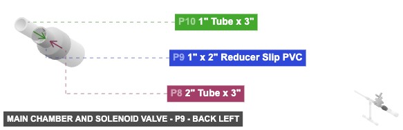
Angle: back left
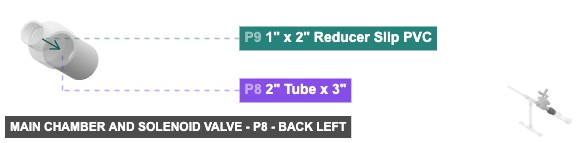
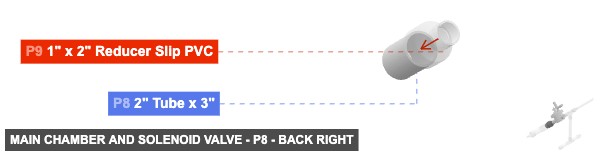
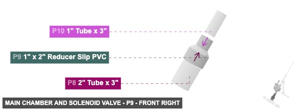
P8 (2" Tube 3" length) - attach its 2" M SLIP #1 facing back-top to part 9's 2" F SLIP #1. Also, its 2" M SLIP #2, which is front-bottom-facing, should connect to part 1's 2" F SLIP #3
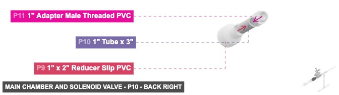
P9 (1" x 2" Reducer Slip PVC) - attach its 1" F SLIP #1 facing back-top to part 10's 1" M SLIP #2. Additionally, connect its 2" F SLIP #1 oriented front-bottom links with part 8's 2" M SLIP #1
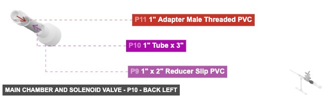
P10 (1" Tube 3" length) - connect its 1" M SLIP #1 oriented back-top links with part 11's 1" F SLIP #1, then its 1" M SLIP #2, which is front-bottom-facing, should connect to part 9's 1" F SLIP #1
P11 (1" Adapter M Threaded PVC) - its 1" M Threaded #1, which is back-top-facing, should connect to part 12's 1" F Threaded #1, and connect its 1" F SLIP #1 oriented front-bottom links with part 10's 1" M SLIP #1
P12 (1" Solenoid Valve) - its 1" F Threaded #1, which is front-bottom-facing, should connect to part 11's 1" M Threaded #1. Next, connect its 1" F Threaded #2 oriented back-top links with part 13's 1" M Threaded #1
2" Tube x 3"x 1 1" x 2" Reducer Slip PVCx 1 1" Tube x 3"x 1 1" Adapter Male Threaded PVCx 1 1" Solenoid Valvex 1
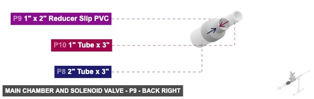
Angle: back right
P8 (2" Tube 3" length) - attach its 2" M SLIP #1 facing back-top to part 9's 2" F SLIP #1. Also, its 2" M SLIP #2, which is front-bottom-facing, should connect to part 1's 2" F SLIP #3
P9 (1" x 2" Reducer Slip PVC) - attach its 1" F SLIP #1 facing back-top to part 10's 1" M SLIP #2. Additionally, connect its 2" F SLIP #1 oriented front-bottom links with part 8's 2" M SLIP #1
P10 (1" Tube 3" length) - connect its 1" M SLIP #1 oriented back-top links with part 11's 1" F SLIP #1, then its 1" M SLIP #2, which is front-bottom-facing, should connect to part 9's 1" F SLIP #1
P11 (1" Adapter M Threaded PVC) - its 1" M Threaded #1, which is back-top-facing, should connect to part 12's 1" F Threaded #1, and connect its 1" F SLIP #1 oriented front-bottom links with part 10's 1" M SLIP #1
P12 (1" Solenoid Valve) - its 1" F Threaded #1, which is front-bottom-facing, should connect to part 11's 1" M Threaded #1. Next, connect its 1" F Threaded #2 oriented back-top links with part 13's 1" M Threaded #1
2" Tube x 3"x 1 1" x 2" Reducer Slip PVCx 1 1" Tube x 3"x 1 1" Adapter Male Threaded PVCx 1 1" Solenoid Valvex 1
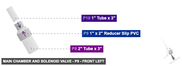
Angle: front left
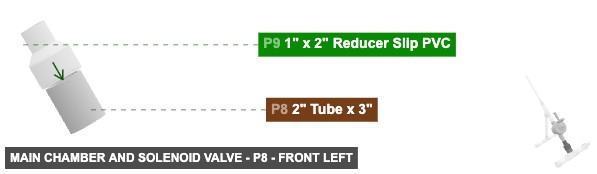
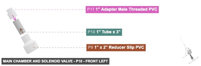
P8 (2" Tube 3" length) - attach its 2" M SLIP #1 facing back-top to part 9's 2" F SLIP #1. Also, its 2" M SLIP #2, which is front-bottom-facing, should connect to part 1's 2" F SLIP #3
P9 (1" x 2" Reducer Slip PVC) - attach its 1" F SLIP #1 facing back-top to part 10's 1" M SLIP #2. Additionally, connect its 2" F SLIP #1 oriented front-bottom links with part 8's 2" M SLIP #1
P10 (1" Tube 3" length) - connect its 1" M SLIP #1 oriented back-top links with part 11's 1" F SLIP #1, then its 1" M SLIP #2, which is front-bottom-facing, should connect to part 9's 1" F SLIP #1
P11 (1" Adapter M Threaded PVC) - its 1" M Threaded #1, which is back-top-facing, should connect to part 12's 1" F Threaded #1, and connect its 1" F SLIP #1 oriented front-bottom links with part 10's 1" M SLIP #1
P12 (1" Solenoid Valve) - its 1" F Threaded #1, which is front-bottom-facing, should connect to part 11's 1" M Threaded #1. Next, connect its 1" F Threaded #2 oriented back-top links with part 13's 1" M Threaded #1
2" Tube x 3"x 1 1" x 2" Reducer Slip PVCx 1 1" Tube x 3"x 1 1" Adapter Male Threaded PVCx 1 1" Solenoid Valvex 1
Angle: front right
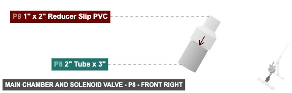
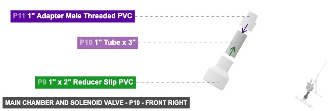
P8 (2" Tube 3" length) - attach its 2" M SLIP #1 facing back-top to part 9's 2" F SLIP #1. Also, its 2" M SLIP #2, which is front-bottom-facing, should connect to part 1's 2" F SLIP #3
P9 (1" x 2" Reducer Slip PVC) - attach its 1" F SLIP #1 facing back-top to part 10's 1" M SLIP #2. Additionally, connect its 2" F SLIP #1 oriented front-bottom links with part 8's 2" M SLIP #1
P10 (1" Tube 3" length) - connect its 1" M SLIP #1 oriented back-top links with part 11's 1" F SLIP #1, then its 1" M SLIP #2, which is front-bottom-facing, should connect to part 9's 1" F SLIP #1
P11 (1" Adapter M Threaded PVC) - its 1" M Threaded #1, which is back-top-facing, should connect to part 12's 1" F Threaded #1, and connect its 1" F SLIP #1 oriented front-bottom links with part 10's 1" M SLIP #1
P12 (1" Solenoid Valve) - its 1" F Threaded #1, which is front-bottom-facing, should connect to part 11's 1" M Threaded #1. Next, connect its 1" F Threaded #2 oriented back-top links with part 13's 1" M Threaded #1
2" Tube x 3"x 1 1" x 2" Reducer Slip PVCx 1 1" Tube x 3"x 1 1" Adapter Male Threaded PVCx 1 1" Solenoid Valvex 1
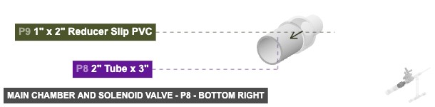
Angle: bottom left
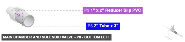
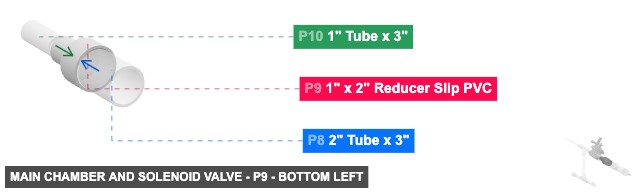
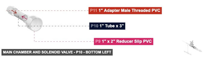
P8 (2" Tube 3" length) - attach its 2" M SLIP #1 facing back-top to part 9's 2" F SLIP #1. Also, its 2" M SLIP #2, which is front-bottom-facing, should connect to part 1's 2" F SLIP #3
P9 (1" x 2" Reducer Slip PVC) - attach its 1" F SLIP #1 facing back-top to part 10's 1" M SLIP #2. Additionally, connect its 2" F SLIP #1 oriented front-bottom links with part 8's 2" M SLIP #1
P10 (1" Tube 3" length) - connect its 1" M SLIP #1 oriented back-top links with part 11's 1" F SLIP #1, then its 1" M SLIP #2, which is front-bottom-facing, should connect to part 9's 1" F SLIP #1
P11 (1" Adapter M Threaded PVC) - its 1" M Threaded #1, which is back-top-facing, should connect to part 12's 1" F Threaded #1, and connect its 1" F SLIP #1 oriented front-bottom links with part 10's 1" M SLIP #1
P12 (1" Solenoid Valve) - its 1" F Threaded #1, which is front-bottom-facing, should connect to part 11's 1" M Threaded #1. Next, connect its 1" F Threaded #2 oriented back-top links with part 13's 1" M Threaded #1
2" Tube x 3"x 1 1" x 2" Reducer Slip PVCx 1 1" Tube x 3"x 1 1" Adapter Male Threaded PVCx 1 1" Solenoid Valvex 1
Angle: bottom right
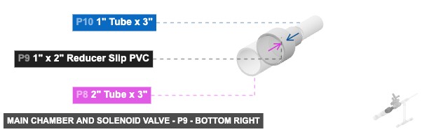
P8 (2" Tube 3" length) - attach its 2" M SLIP #1 facing back-top to part 9's 2" F SLIP #1. Also, its 2" M SLIP #2, which is front-bottom-facing, should connect to part 1's 2" F SLIP #3
P9 (1" x 2" Reducer Slip PVC) - attach its 1" F SLIP #1 facing back-top to part 10's 1" M SLIP #2. Additionally, connect its 2" F SLIP #1 oriented front-bottom links with part 8's 2" M SLIP #1
P10 (1" Tube 3" length) - connect its 1" M SLIP #1 oriented back-top links with part 11's 1" F SLIP #1, then its 1" M SLIP #2, which is front-bottom-facing, should connect to part 9's 1" F SLIP #1
P11 (1" Adapter M Threaded PVC) - its 1" M Threaded #1, which is back-top-facing, should connect to part 12's 1" F Threaded #1, and connect its 1" F SLIP #1 oriented front-bottom links with part 10's 1" M SLIP #1
P12 (1" Solenoid Valve) - its 1" F Threaded #1, which is front-bottom-facing, should connect to part 11's 1" M Threaded #1. Next, connect its 1" F Threaded #2 oriented back-top links with part 13's 1" M Threaded #1
2" Tube x 3"x 1 1" x 2" Reducer Slip PVCx 1 1" Tube x 3"x 1 1" Adapter Male Threaded PVCx 1 1" Solenoid Valvex 1 Attaching: Post-Valve Transition and Wye
Connects the solenoid valve output, splitting the path towards the launch tube and the stand using a Wye fitting.
Connect the bottom 1" Female SLIP of P15 to the Stand Assembly (starting with P16). Connect the back-top 1" Female SLIP of P15 to the Launch Tube Assembly (starting with P21).
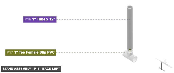
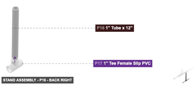
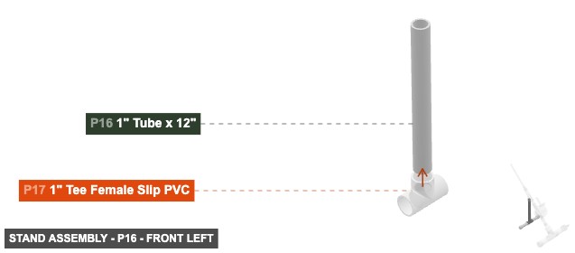
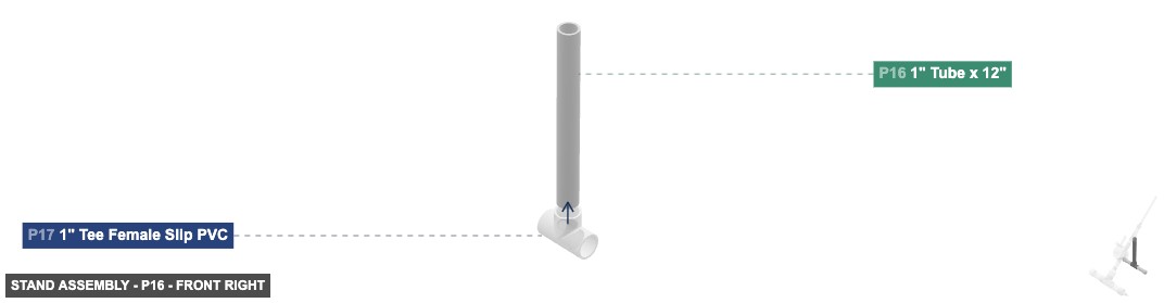
Attaching: Stand Assembly
Creates the T-shaped base stand for the launcher.
Connect the top 1" Male SLIP of P16 into the bottom 1" Female SLIP of the Post-Valve Transition Assembly (P15).
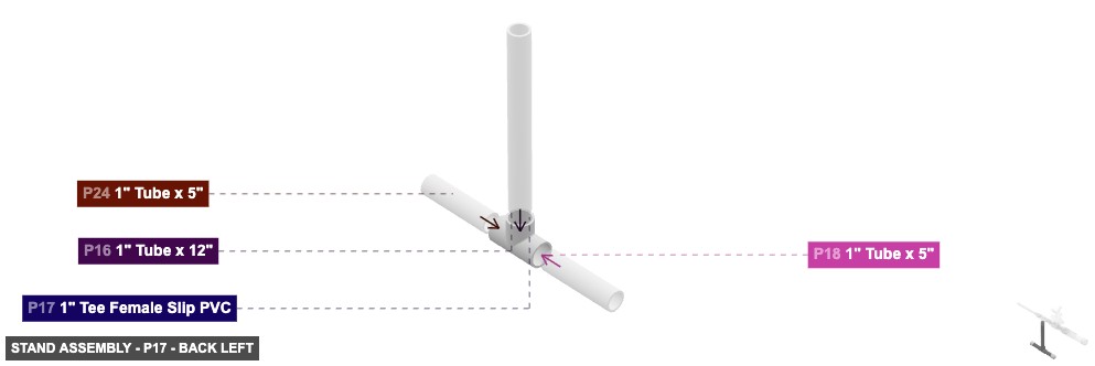
Angle: back left
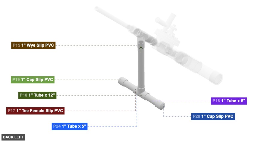
P16 (1" Tube 12" length) - connect its 1" M SLIP #1 oriented bottom links with part 17's 1" F SLIP #3. After that, its 1" M SLIP #2, which is top-facing, should connect to part 15's 1" F SLIP #3
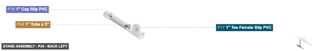
P17 (1" Tee F Slip PVC) - connect its 1" F SLIP #1 oriented left links with part 18's 1" M SLIP #2, plus its 1" F SLIP #2, which is right-facing, should connect to part 24's 1" M SLIP #2. After that, attach its 1" F SLIP #3 facing top to part 16's 1" M SLIP #1
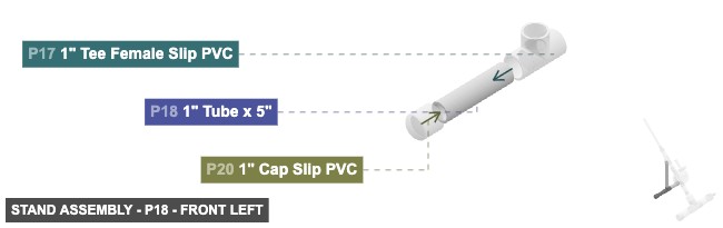
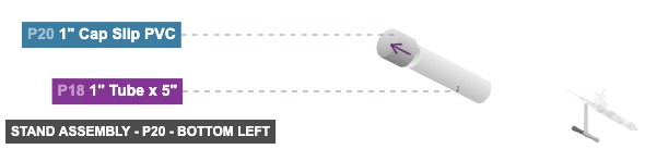
P18 (1" Tube 5" length) - attach its 1" M SLIP #1 facing left to part 20's 1" F SLIP #1, and connect its 1" M SLIP #2 oriented right links with part 17's 1" F SLIP #1
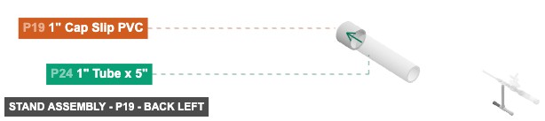
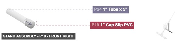
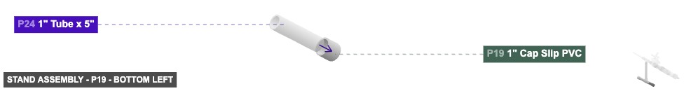
P19 (1" Cap Slip PVC) - attach its 1" F SLIP #1 facing left to part 24's 1" M SLIP #1
P20 (1" Cap Slip PVC) - its 1" F SLIP #1, which is right-facing, should connect to part 18's 1" M SLIP #1
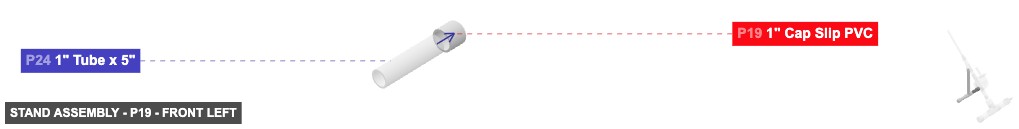
P24 (1" Tube 5" length) - attach its 1" M SLIP #1 facing right to part 19's 1" F SLIP #1, plus attach its 1" M SLIP #2 facing left to part 17's 1" F SLIP #2
1" Tube x 12"x 1 1" Tee Female Slip PVCx 1 1" Tube x 5"x 2 1" Cap Slip PVCx 2
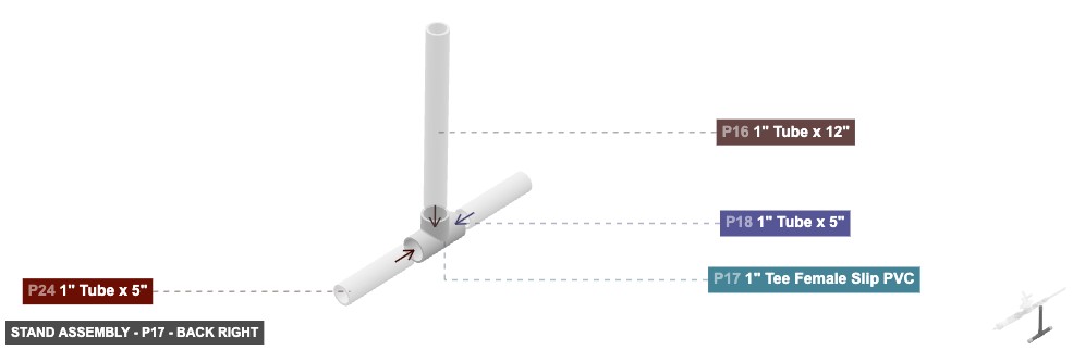
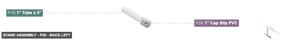
Angle: back right
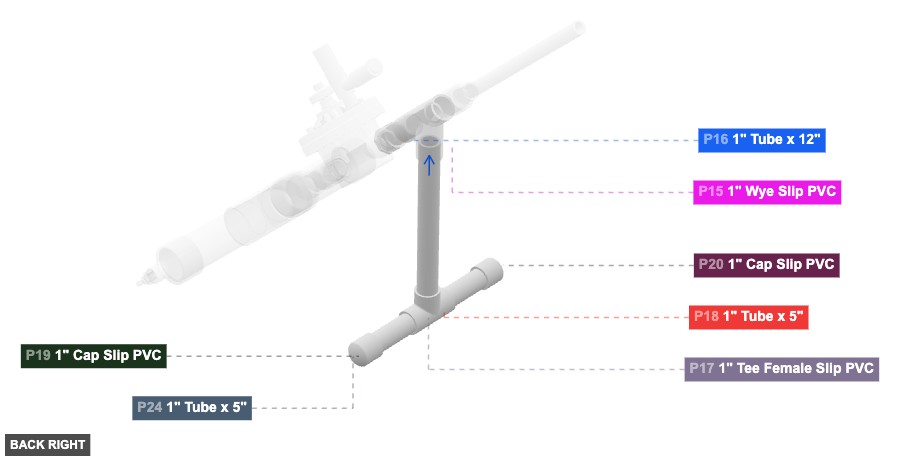
P16 (1" Tube 12" length) - connect its 1" M SLIP #1 oriented bottom links with part 17's 1" F SLIP #3. After that, its 1" M SLIP #2, which is top-facing, should connect to part 15's 1" F SLIP #3
P17 (1" Tee F Slip PVC) - connect its 1" F SLIP #1 oriented left links with part 18's 1" M SLIP #2, plus its 1" F SLIP #2, which is right-facing, should connect to part 24's 1" M SLIP #2. After that, attach its 1" F SLIP #3 facing top to part 16's 1" M SLIP #1
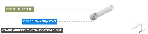
P18 (1" Tube 5" length) - attach its 1" M SLIP #1 facing left to part 20's 1" F SLIP #1, and connect its 1" M SLIP #2 oriented right links with part 17's 1" F SLIP #1
P19 (1" Cap Slip PVC) - attach its 1" F SLIP #1 facing left to part 24's 1" M SLIP #1
P20 (1" Cap Slip PVC) - its 1" F SLIP #1, which is right-facing, should connect to part 18's 1" M SLIP #1
P24 (1" Tube 5" length) - attach its 1" M SLIP #1 facing right to part 19's 1" F SLIP #1, plus attach its 1" M SLIP #2 facing left to part 17's 1" F SLIP #2
1" Tube x 12"x 1 1" Tee Female Slip PVCx 1 1" Tube x 5"x 2 1" Cap Slip PVCx 2
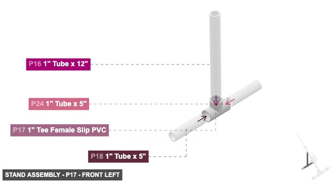
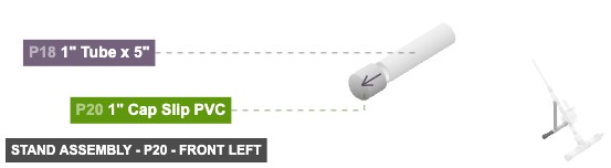
Angle: front left
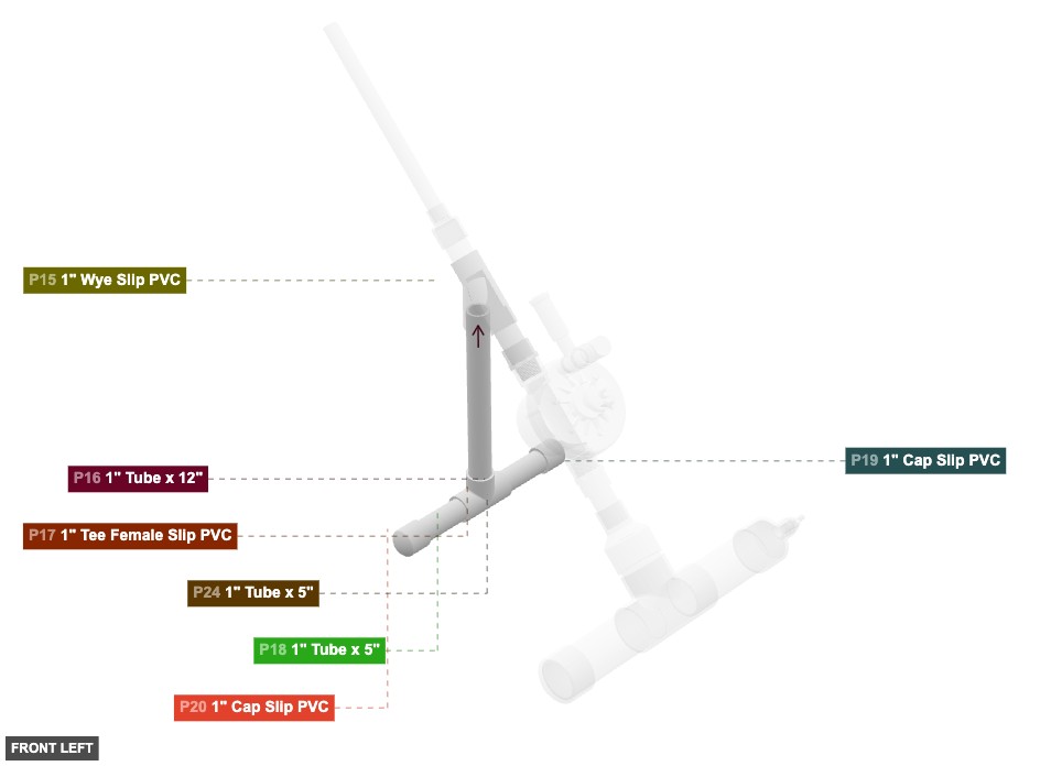
P16 (1" Tube 12" length) - connect its 1" M SLIP #1 oriented bottom links with part 17's 1" F SLIP #3. After that, its 1" M SLIP #2, which is top-facing, should connect to part 15's 1" F SLIP #3
P17 (1" Tee F Slip PVC) - connect its 1" F SLIP #1 oriented left links with part 18's 1" M SLIP #2, plus its 1" F SLIP #2, which is right-facing, should connect to part 24's 1" M SLIP #2. After that, attach its 1" F SLIP #3 facing top to part 16's 1" M SLIP #1
P18 (1" Tube 5" length) - attach its 1" M SLIP #1 facing left to part 20's 1" F SLIP #1, and connect its 1" M SLIP #2 oriented right links with part 17's 1" F SLIP #1
P19 (1" Cap Slip PVC) - attach its 1" F SLIP #1 facing left to part 24's 1" M SLIP #1
P20 (1" Cap Slip PVC) - its 1" F SLIP #1, which is right-facing, should connect to part 18's 1" M SLIP #1
P24 (1" Tube 5" length) - attach its 1" M SLIP #1 facing right to part 19's 1" F SLIP #1, plus attach its 1" M SLIP #2 facing left to part 17's 1" F SLIP #2
1" Tube x 12"x 1 1" Tee Female Slip PVCx 1 1" Tube x 5"x 2 1" Cap Slip PVCx 2
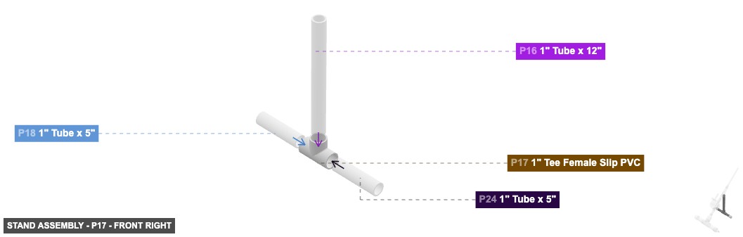
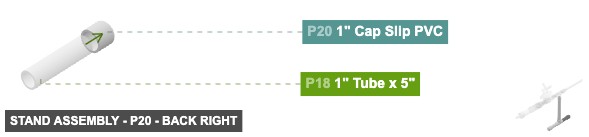
Angle: front right
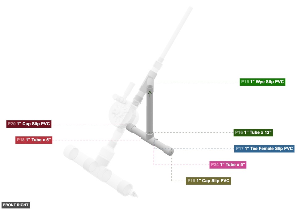
P16 (1" Tube 12" length) - connect its 1" M SLIP #1 oriented bottom links with part 17's 1" F SLIP #3. After that, its 1" M SLIP #2, which is top-facing, should connect to part 15's 1" F SLIP #3
P17 (1" Tee F Slip PVC) - connect its 1" F SLIP #1 oriented left links with part 18's 1" M SLIP #2, plus its 1" F SLIP #2, which is right-facing, should connect to part 24's 1" M SLIP #2. After that, attach its 1" F SLIP #3 facing top to part 16's 1" M SLIP #1
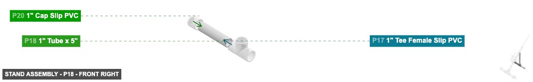
P18 (1" Tube 5" length) - attach its 1" M SLIP #1 facing left to part 20's 1" F SLIP #1, and connect its 1" M SLIP #2 oriented right links with part 17's 1" F SLIP #1
P19 (1" Cap Slip PVC) - attach its 1" F SLIP #1 facing left to part 24's 1" M SLIP #1
P20 (1" Cap Slip PVC) - its 1" F SLIP #1, which is right-facing, should connect to part 18's 1" M SLIP #1
P24 (1" Tube 5" length) - attach its 1" M SLIP #1 facing right to part 19's 1" F SLIP #1, plus attach its 1" M SLIP #2 facing left to part 17's 1" F SLIP #2
1" Tube x 12"x 1 1" Tee Female Slip PVCx 1 1" Tube x 5"x 2 1" Cap Slip PVCx 2
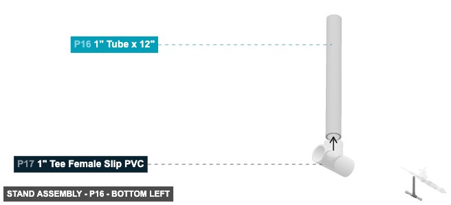
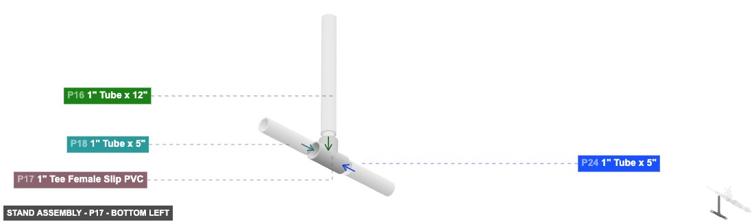
Angle: bottom left
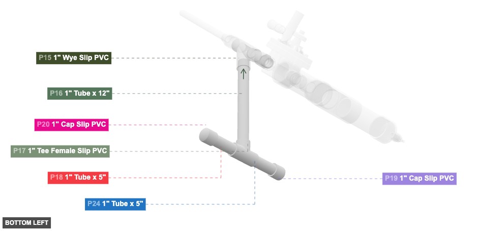
P16 (1" Tube 12" length) - connect its 1" M SLIP #1 oriented bottom links with part 17's 1" F SLIP #3. After that, its 1" M SLIP #2, which is top-facing, should connect to part 15's 1" F SLIP #3
P17 (1" Tee F Slip PVC) - connect its 1" F SLIP #1 oriented left links with part 18's 1" M SLIP #2, plus its 1" F SLIP #2, which is right-facing, should connect to part 24's 1" M SLIP #2. After that, attach its 1" F SLIP #3 facing top to part 16's 1" M SLIP #1
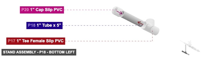
P18 (1" Tube 5" length) - attach its 1" M SLIP #1 facing left to part 20's 1" F SLIP #1, and connect its 1" M SLIP #2 oriented right links with part 17's 1" F SLIP #1
P19 (1" Cap Slip PVC) - attach its 1" F SLIP #1 facing left to part 24's 1" M SLIP #1
P20 (1" Cap Slip PVC) - its 1" F SLIP #1, which is right-facing, should connect to part 18's 1" M SLIP #1
P24 (1" Tube 5" length) - attach its 1" M SLIP #1 facing right to part 19's 1" F SLIP #1, plus attach its 1" M SLIP #2 facing left to part 17's 1" F SLIP #2
1" Tube x 12"x 1 1" Tee Female Slip PVCx 1 1" Tube x 5"x 2 1" Cap Slip PVCx 2
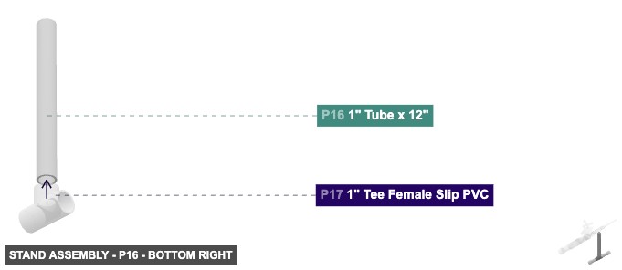
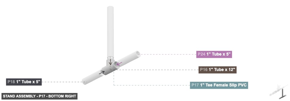
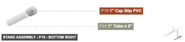
Angle: bottom right
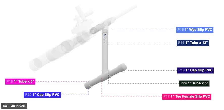
P16 (1" Tube 12" length) - connect its 1" M SLIP #1 oriented bottom links with part 17's 1" F SLIP #3. After that, its 1" M SLIP #2, which is top-facing, should connect to part 15's 1" F SLIP #3
P17 (1" Tee F Slip PVC) - connect its 1" F SLIP #1 oriented left links with part 18's 1" M SLIP #2, plus its 1" F SLIP #2, which is right-facing, should connect to part 24's 1" M SLIP #2. After that, attach its 1" F SLIP #3 facing top to part 16's 1" M SLIP #1
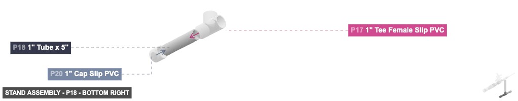
P18 (1" Tube 5" length) - attach its 1" M SLIP #1 facing left to part 20's 1" F SLIP #1, and connect its 1" M SLIP #2 oriented right links with part 17's 1" F SLIP #1
P19 (1" Cap Slip PVC) - attach its 1" F SLIP #1 facing left to part 24's 1" M SLIP #1
P20 (1" Cap Slip PVC) - its 1" F SLIP #1, which is right-facing, should connect to part 18's 1" M SLIP #1
P24 (1" Tube 5" length) - attach its 1" M SLIP #1 facing right to part 19's 1" F SLIP #1, plus attach its 1" M SLIP #2 facing left to part 17's 1" F SLIP #2
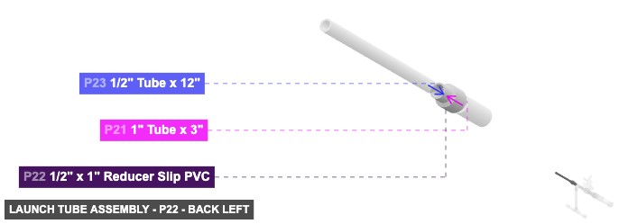
1" Tube x 12"x 1 1" Tee Female Slip PVCx 1 1" Tube x 5"x 2 1" Cap Slip PVCx 2 Attaching: Launch Tube Assembly
Forms the final launch tube where the rocket is placed.
Connect the bottom 1" Male SLIP of P21 into the back-top 1" Female SLIP of the Post-Valve Transition Assembly (P15).