Potato Gun - Comprehensive Assembly Plan And Visual Guide
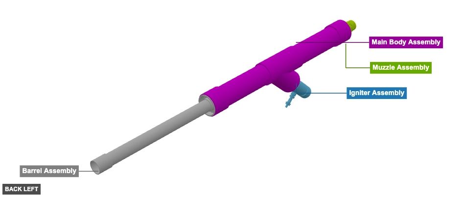
A potato gun constructed primarily from PVC pipes and fittings. It features a main barrel, a parallel combustion chamber, a Wye connector joining them, an igniter assembly at the rear of the combustion chamber, and a muzzle assembly at the front. - Potato Gun
Phase 1: Group Overview
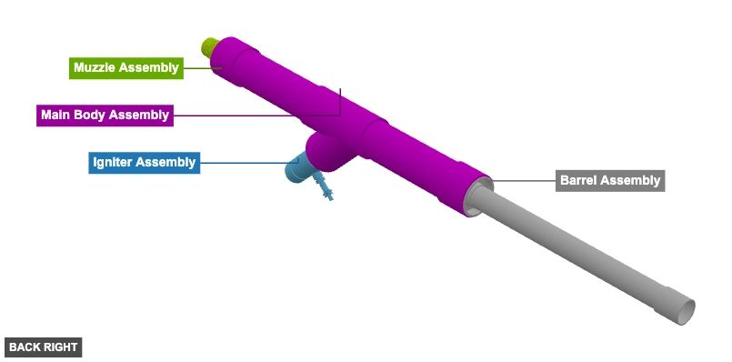
Angle: back left

Igniter Assembly
 2" x 4" Reducer Slip PVCx 1
 2" Tube x 3"x 2
 2" x 1/2" Reducer Tee Female Threaded PVCx 1
 1/2" x 1/4" Bushing Male Threaded PVCx 1
 Igniter Spark Plug with 1/4" Male Threaded Connectionx 1
 2" Cap Slip PVCx 1
Barrel Assembly
2" Tube x 25.34"x 1  2" Coupler Slip PVCx 1
2" x 4" Reducer Slip PVC DWVx 1 Muzzle Assembly
2" x 4" Reducer Slip PVC DWVx 1  1-1/2" x 2" Nipplex 1
 1-1/2" Cap Threaded PVC x 1
 1-1/2" x 2" Bushing Male Slip PVCx 1
Main Body Assembly
 4" PVC Tube x 15"x 2
 4" Wye Slip PVCx 1
 4¨ Coupler H x H PVC DWVx 2
Angle: back right
Igniter Assembly
2" x 4" Reducer Slip PVCx 1 2" Tube x 3"x 2 2" x 1/2" Reducer Tee Female Threaded PVCx 1 1/2" x 1/4" Bushing Male Threaded PVCx 1 Igniter Spark Plug with 1/4" Male Threaded Connectionx 1 2" Cap Slip PVCx 1 Barrel Assembly
2" Tube x 25.34"x 1 2" Coupler Slip PVCx 1 2" x 4" Reducer Slip PVC DWVx 1 Muzzle Assembly
2" x 4" Reducer Slip PVC DWVx 1 1-1/2" x 2" Nipplex 1 1-1/2" Cap Threaded PVC x 1 1-1/2" x 2" Bushing Male Slip PVCx 1 Main Body Assembly
4" PVC Tube x 15"x 2 4" Wye Slip PVCx 1 4¨ Coupler H x H PVC DWVx 2
Angle: front left
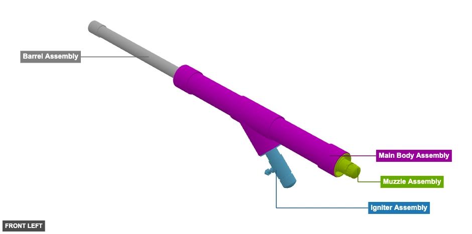
Igniter Assembly
2" x 4" Reducer Slip PVCx 1 2" Tube x 3"x 2 2" x 1/2" Reducer Tee Female Threaded PVCx 1 1/2" x 1/4" Bushing Male Threaded PVCx 1 Igniter Spark Plug with 1/4" Male Threaded Connectionx 1 2" Cap Slip PVCx 1 Barrel Assembly
2" Tube x 25.34"x 1 2" Coupler Slip PVCx 1 2" x 4" Reducer Slip PVC DWVx 1 Muzzle Assembly
2" x 4" Reducer Slip PVC DWVx 1 1-1/2" x 2" Nipplex 1 1-1/2" Cap Threaded PVC x 1 1-1/2" x 2" Bushing Male Slip PVCx 1 Main Body Assembly
4" PVC Tube x 15"x 2 4" Wye Slip PVCx 1 4¨ Coupler H x H PVC DWVx 2
Angle: front right
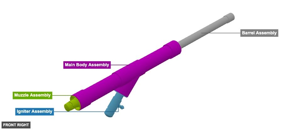
Igniter Assembly
2" x 4" Reducer Slip PVCx 1 2" Tube x 3"x 2 2" x 1/2" Reducer Tee Female Threaded PVCx 1 1/2" x 1/4" Bushing Male Threaded PVCx 1 Igniter Spark Plug with 1/4" Male Threaded Connectionx 1 2" Cap Slip PVCx 1 Barrel Assembly
2" Tube x 25.34"x 1 2" Coupler Slip PVCx 1 2" x 4" Reducer Slip PVC DWVx 1 Muzzle Assembly
2" x 4" Reducer Slip PVC DWVx 1 1-1/2" x 2" Nipplex 1 1-1/2" Cap Threaded PVC x 1 1-1/2" x 2" Bushing Male Slip PVCx 1 Main Body Assembly
4" PVC Tube x 15"x 2 4" Wye Slip PVCx 1 4¨ Coupler H x H PVC DWVx 2
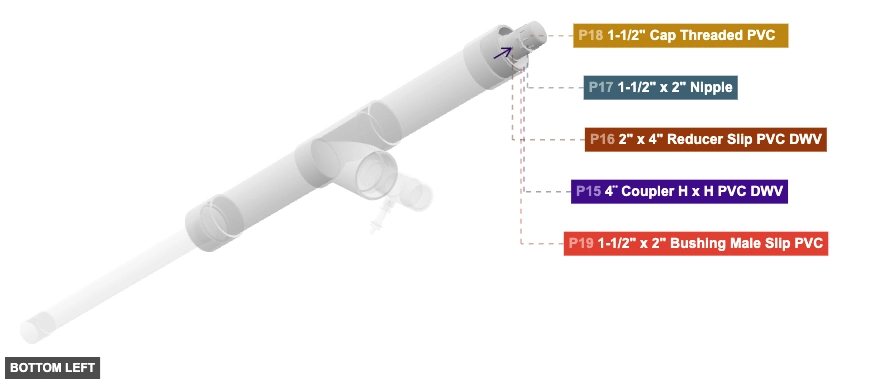
Angle: bottom left
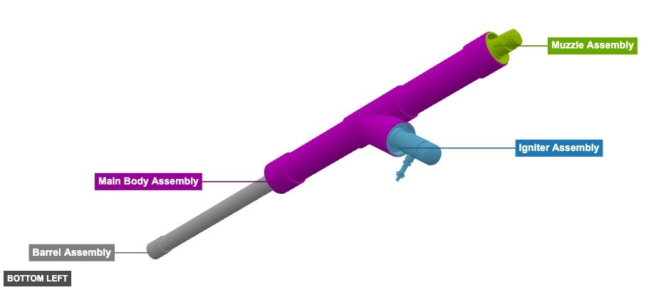
Igniter Assembly
2" x 4" Reducer Slip PVCx 1 2" Tube x 3"x 2 2" x 1/2" Reducer Tee Female Threaded PVCx 1 1/2" x 1/4" Bushing Male Threaded PVCx 1 Igniter Spark Plug with 1/4" Male Threaded Connectionx 1 2" Cap Slip PVCx 1 Barrel Assembly
2" Tube x 25.34"x 1 2" Coupler Slip PVCx 1 2" x 4" Reducer Slip PVC DWVx 1 Muzzle Assembly
2" x 4" Reducer Slip PVC DWVx 1 1-1/2" x 2" Nipplex 1 1-1/2" Cap Threaded PVC x 1 1-1/2" x 2" Bushing Male Slip PVCx 1 Main Body Assembly
4" PVC Tube x 15"x 2 4" Wye Slip PVCx 1 4¨ Coupler H x H PVC DWVx 2
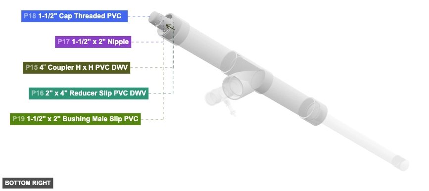
Angle: bottom right
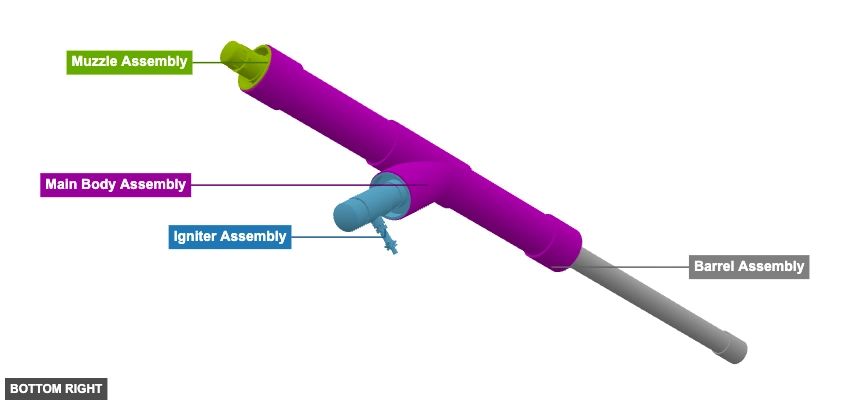
Igniter Assembly
2" x 4" Reducer Slip PVCx 1 2" Tube x 3"x 2 2" x 1/2" Reducer Tee Female Threaded PVCx 1 1/2" x 1/4" Bushing Male Threaded PVCx 1 Igniter Spark Plug with 1/4" Male Threaded Connectionx 1 2" Cap Slip PVCx 1 Barrel Assembly
2" Tube x 25.34"x 1 2" Coupler Slip PVCx 1 2" x 4" Reducer Slip PVC DWVx 1 Muzzle Assembly
2" x 4" Reducer Slip PVC DWVx 1 1-1/2" x 2" Nipplex 1 1-1/2" Cap Threaded PVC x 1 1-1/2" x 2" Bushing Male Slip PVCx 1 Main Body Assembly
4" PVC Tube x 15"x 2 4" Wye Slip PVCx 1 4¨ Coupler H x H PVC DWVx 2 Phase 2: Individual Group Assembly
Group: Igniter Assembly
Forms the base of the combustion chamber and houses the igniter mechanism.
Connect P7 (Igniter Spark Plug) 1/4" Male Threaded connection to P6 (Bushing) 1/4" Female Threaded connection. Connect P6's 1/2" Male Threaded connection to P4 (Reducer Tee) 1/2" Female Threaded connection (facing back-bottom). Connect P3 (Tube) 2" Male SLIP (facing front-bottom) to P4's 2" Female SLIP (facing back-top). Connect P5 (Tube) 2" Male SLIP (facing back-top) to P4's 2" Female SLIP (facing front-bottom). Connect P2 (Reducer) 2" Female SLIP (facing front-bottom) to P3's 2" Male SLIP (facing back-top). Connect P8 (Cap) 2" Female SLIP to P5's 2" Male SLIP (facing front-bottom).
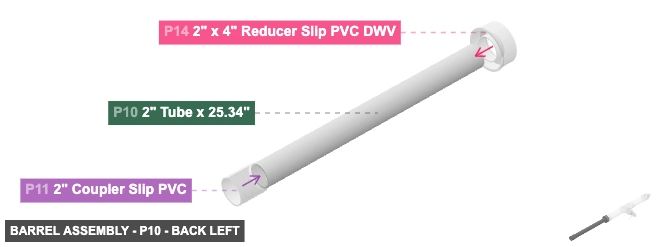
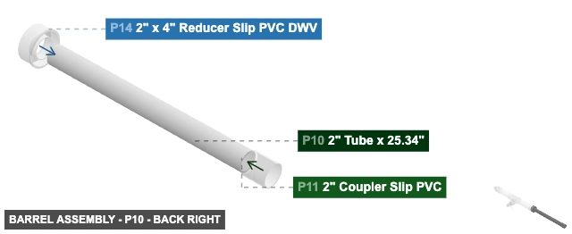
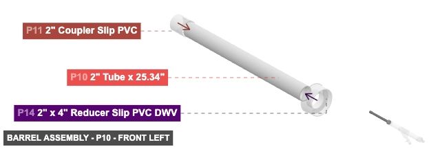
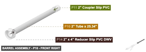
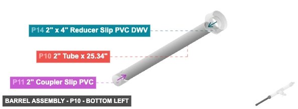
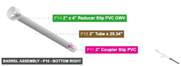
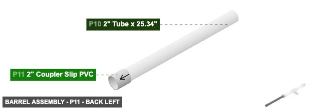
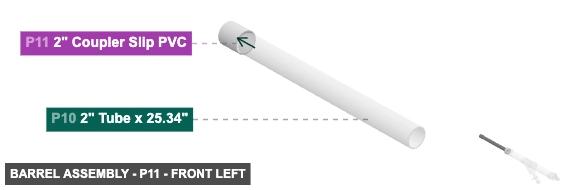
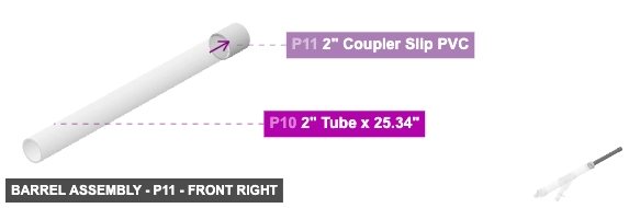
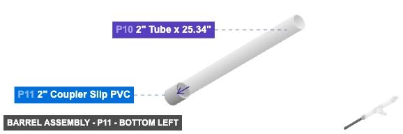
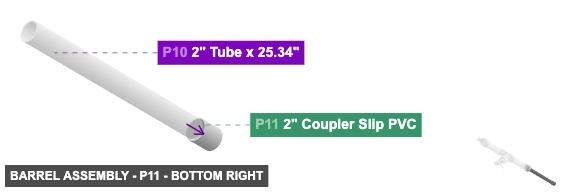
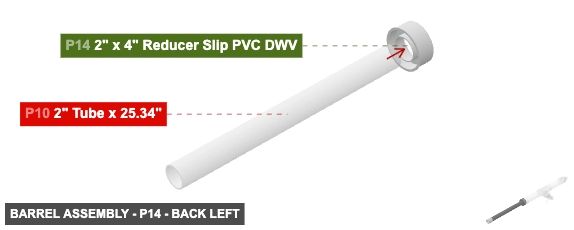
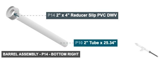
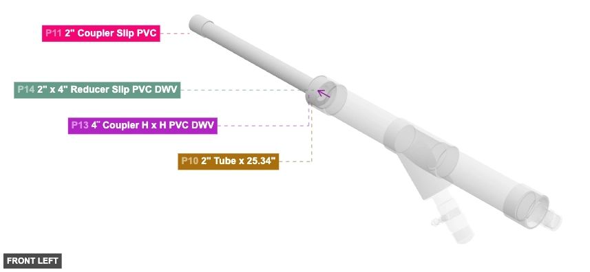
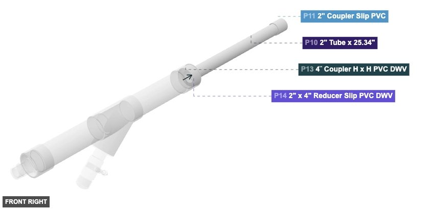
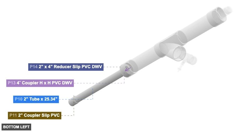
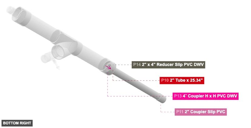
Group: Barrel Assembly
Creates the main barrel tube with its connecting fittings.
Attach P11 (Coupler) 2" Female SLIP (facing front) to P10 (Tube) 2" Male SLIP (facing back). Attach P14 (Reducer) 2" Female SLIP (facing back) to P10's 2" Male SLIP (facing front).
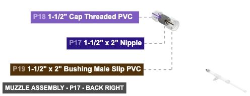
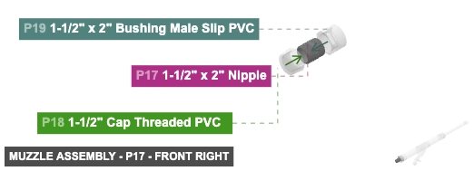
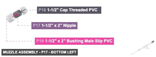
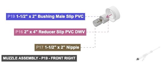
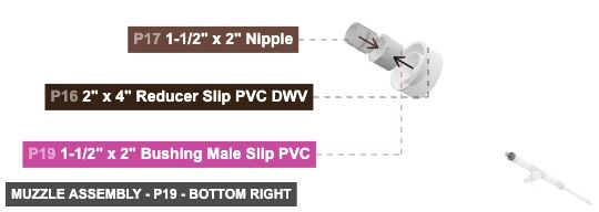
Group: Muzzle Assembly
Creates the muzzle end cap/fitting for the combustion chamber side.
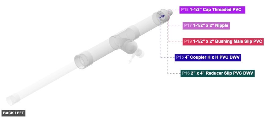
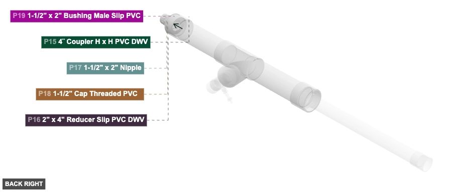
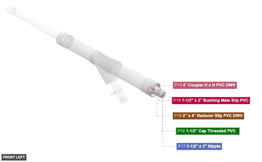
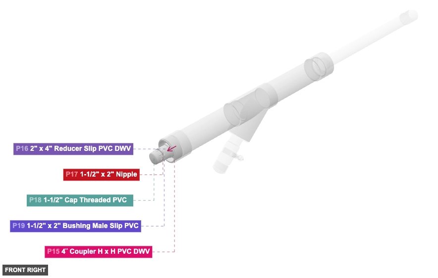
Connect P17 (Nipple) 1 1/2" Male Threaded connection (facing back) to P19 (Bushing) 1 1/2" Female Threaded connection (facing front). Attach P18 (Cap) 1 1/2" Female Threaded connection to P17's 1 1/2" Male Threaded connection (facing front). Attach P19's 2" Male SLIP (facing back) to P16 (Reducer) 2" Female SLIP connection (facing front).
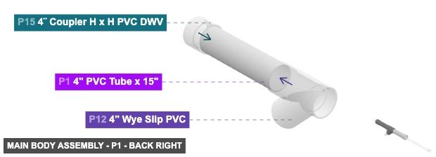
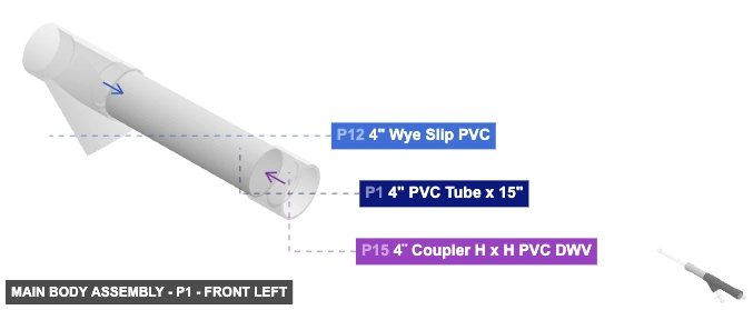
Group: Main Body Assembly
Connects the main structural tubes and integrates the Igniter, Barrel, and Muzzle sub-assemblies.
Connect P1 (Tube) 4" Male SLIP (facing back) to P12 (Wye) 4" Female SLIP (facing front). Connect P9 (Tube) 4" Male SLIP (facing front) to P12's 4" Female SLIP (facing back). Connect P13 (Coupler) 4" DWV Female connection (facing front) to P9's 4" Male SLIP (facing back). Connect P15 (Coupler) 4" DWV Female connection (facing back) to P1's 4" Male SLIP (facing front).
Phase 3: Inter-Group Assembly
Attaching: Igniter Assembly
Forms the base of the combustion chamber and houses the igniter mechanism.
The completed Igniter Assembly connects via P2's 4" Male SLIP (facing back-top) to the Main Body Assembly (P12).
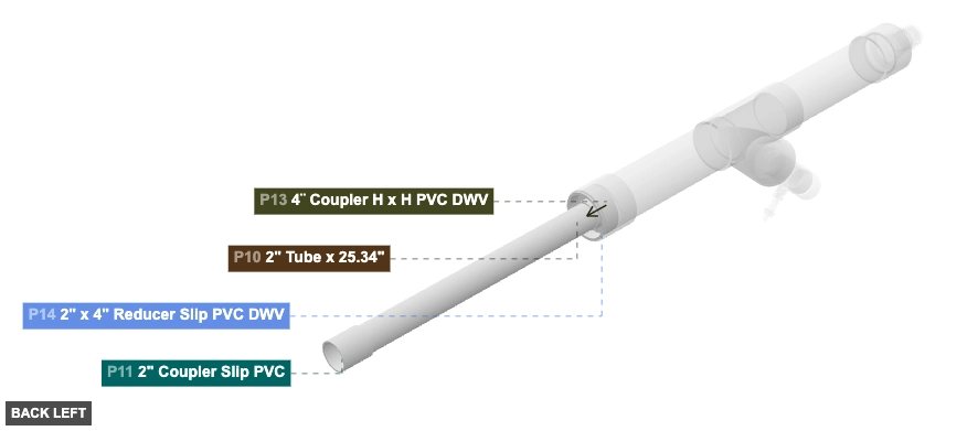
Angle: back left
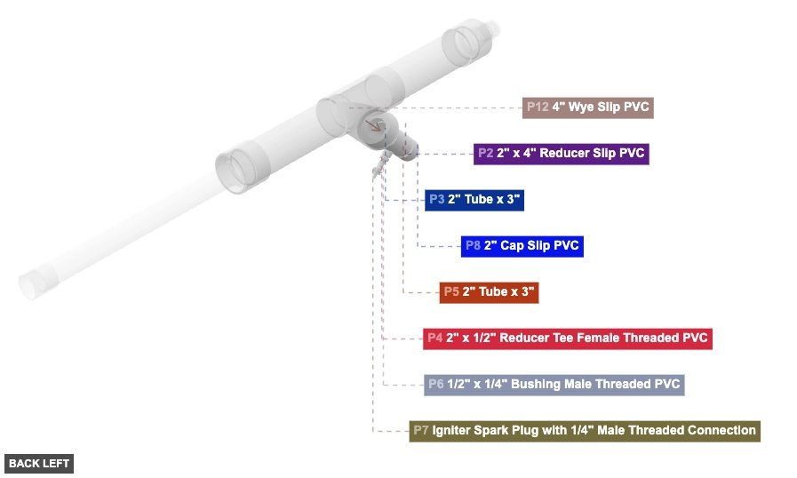
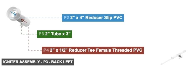
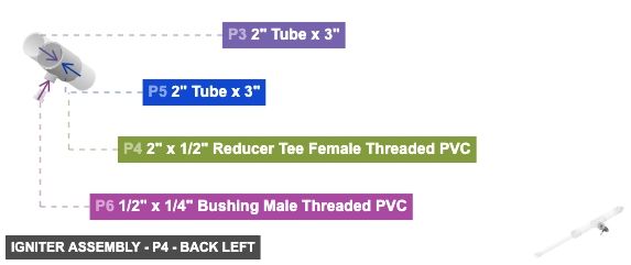
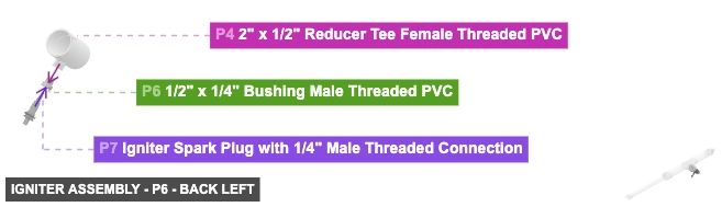
P2 (2" x 4" Reducer Slip PVC) - attach its 2" F SLIP #1 facing front-bottom to part 3's 2" M SLIP #2. Also, attach its 4" M SLIP #1 facing back-top to part 12's 4" F SLIP #2
P3 (2" Tube 3" length) - attach its 2" M SLIP #1 facing front-bottom to part 4's 2" F SLIP #1. Also, connect its 2" M SLIP #2 oriented back-top links with part 2's 2" F SLIP #1
P4 (2" x 1/2" Reducer Tee F Threaded PVC) - attach its 2" F SLIP #1 facing back-top to part 3's 2" M SLIP #1. Next, connect its 2" F SLIP #2 oriented front-bottom links with part 5's 2" M SLIP #2. Also, connect its 0.5" F Threaded #1 oriented back-bottom links with part 6's 0.5" M Threaded #1
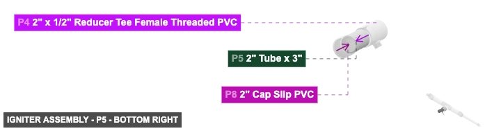
P5 (2" Tube 3" length) - attach its 2" M SLIP #1 facing front-bottom to part 8's 2" F SLIP #1, also connect its 2" M SLIP #2 oriented back-top links with part 4's 2" F SLIP #2
P6 (0.5" x 1/4" Bushing M Threaded PVC) - connect its 0.5" M Threaded #1 oriented front-top links with part 4's 0.5" F Threaded #1. Next, connect its 0.25" F Threaded #1 oriented back-bottom links with part 7's 0.25" M Threaded #1
P7 (Igniter Spark Plug with M Threaded Connection) - its 0.25" M Threaded #1, which is front-top-facing, should connect to part 6's 0.25" F Threaded #1
P8 (2" Cap Slip PVC) - its 2" F SLIP #1, which is back-top-facing, should connect to part 5's 2" M SLIP #1
2" x 4" Reducer Slip PVCx 1 2" Tube x 3"x 2 2" x 1/2" Reducer Tee Female Threaded PVCx 1 1/2" x 1/4" Bushing Male Threaded PVCx 1 Igniter Spark Plug with 1/4" Male Threaded Connectionx 1 2" Cap Slip PVCx 1
Angle: back right
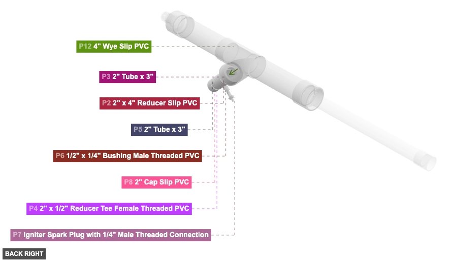
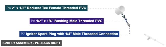
P2 (2" x 4" Reducer Slip PVC) - attach its 2" F SLIP #1 facing front-bottom to part 3's 2" M SLIP #2. Also, attach its 4" M SLIP #1 facing back-top to part 12's 4" F SLIP #2
P3 (2" Tube 3" length) - attach its 2" M SLIP #1 facing front-bottom to part 4's 2" F SLIP #1. Also, connect its 2" M SLIP #2 oriented back-top links with part 2's 2" F SLIP #1
P4 (2" x 1/2" Reducer Tee F Threaded PVC) - attach its 2" F SLIP #1 facing back-top to part 3's 2" M SLIP #1. Next, connect its 2" F SLIP #2 oriented front-bottom links with part 5's 2" M SLIP #2. Also, connect its 0.5" F Threaded #1 oriented back-bottom links with part 6's 0.5" M Threaded #1
P5 (2" Tube 3" length) - attach its 2" M SLIP #1 facing front-bottom to part 8's 2" F SLIP #1, also connect its 2" M SLIP #2 oriented back-top links with part 4's 2" F SLIP #2
P6 (0.5" x 1/4" Bushing M Threaded PVC) - connect its 0.5" M Threaded #1 oriented front-top links with part 4's 0.5" F Threaded #1. Next, connect its 0.25" F Threaded #1 oriented back-bottom links with part 7's 0.25" M Threaded #1
P7 (Igniter Spark Plug with M Threaded Connection) - its 0.25" M Threaded #1, which is front-top-facing, should connect to part 6's 0.25" F Threaded #1
P8 (2" Cap Slip PVC) - its 2" F SLIP #1, which is back-top-facing, should connect to part 5's 2" M SLIP #1
2" x 4" Reducer Slip PVCx 1 2" Tube x 3"x 2 2" x 1/2" Reducer Tee Female Threaded PVCx 1 1/2" x 1/4" Bushing Male Threaded PVCx 1 Igniter Spark Plug with 1/4" Male Threaded Connectionx 1 2" Cap Slip PVCx 1
Angle: front left
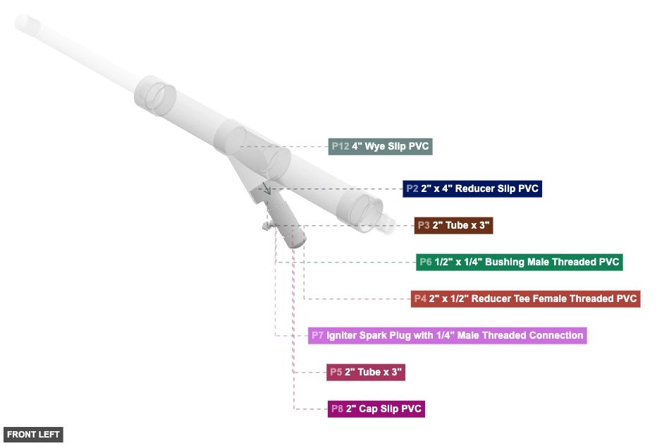
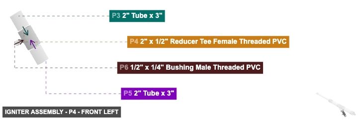
P2 (2" x 4" Reducer Slip PVC) - attach its 2" F SLIP #1 facing front-bottom to part 3's 2" M SLIP #2. Also, attach its 4" M SLIP #1 facing back-top to part 12's 4" F SLIP #2
P3 (2" Tube 3" length) - attach its 2" M SLIP #1 facing front-bottom to part 4's 2" F SLIP #1. Also, connect its 2" M SLIP #2 oriented back-top links with part 2's 2" F SLIP #1
P4 (2" x 1/2" Reducer Tee F Threaded PVC) - attach its 2" F SLIP #1 facing back-top to part 3's 2" M SLIP #1. Next, connect its 2" F SLIP #2 oriented front-bottom links with part 5's 2" M SLIP #2. Also, connect its 0.5" F Threaded #1 oriented back-bottom links with part 6's 0.5" M Threaded #1
P5 (2" Tube 3" length) - attach its 2" M SLIP #1 facing front-bottom to part 8's 2" F SLIP #1, also connect its 2" M SLIP #2 oriented back-top links with part 4's 2" F SLIP #2
P6 (0.5" x 1/4" Bushing M Threaded PVC) - connect its 0.5" M Threaded #1 oriented front-top links with part 4's 0.5" F Threaded #1. Next, connect its 0.25" F Threaded #1 oriented back-bottom links with part 7's 0.25" M Threaded #1
P7 (Igniter Spark Plug with M Threaded Connection) - its 0.25" M Threaded #1, which is front-top-facing, should connect to part 6's 0.25" F Threaded #1
P8 (2" Cap Slip PVC) - its 2" F SLIP #1, which is back-top-facing, should connect to part 5's 2" M SLIP #1
2" x 4" Reducer Slip PVCx 1 2" Tube x 3"x 2 2" x 1/2" Reducer Tee Female Threaded PVCx 1 1/2" x 1/4" Bushing Male Threaded PVCx 1 Igniter Spark Plug with 1/4" Male Threaded Connectionx 1 2" Cap Slip PVCx 1
Angle: front right
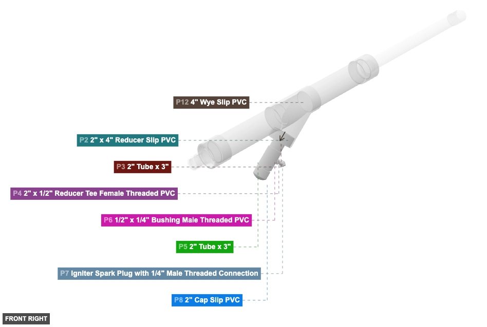
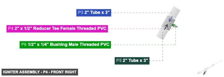
P2 (2" x 4" Reducer Slip PVC) - attach its 2" F SLIP #1 facing front-bottom to part 3's 2" M SLIP #2. Also, attach its 4" M SLIP #1 facing back-top to part 12's 4" F SLIP #2
P3 (2" Tube 3" length) - attach its 2" M SLIP #1 facing front-bottom to part 4's 2" F SLIP #1. Also, connect its 2" M SLIP #2 oriented back-top links with part 2's 2" F SLIP #1
P4 (2" x 1/2" Reducer Tee F Threaded PVC) - attach its 2" F SLIP #1 facing back-top to part 3's 2" M SLIP #1. Next, connect its 2" F SLIP #2 oriented front-bottom links with part 5's 2" M SLIP #2. Also, connect its 0.5" F Threaded #1 oriented back-bottom links with part 6's 0.5" M Threaded #1
P5 (2" Tube 3" length) - attach its 2" M SLIP #1 facing front-bottom to part 8's 2" F SLIP #1, also connect its 2" M SLIP #2 oriented back-top links with part 4's 2" F SLIP #2
P6 (0.5" x 1/4" Bushing M Threaded PVC) - connect its 0.5" M Threaded #1 oriented front-top links with part 4's 0.5" F Threaded #1. Next, connect its 0.25" F Threaded #1 oriented back-bottom links with part 7's 0.25" M Threaded #1
P7 (Igniter Spark Plug with M Threaded Connection) - its 0.25" M Threaded #1, which is front-top-facing, should connect to part 6's 0.25" F Threaded #1
P8 (2" Cap Slip PVC) - its 2" F SLIP #1, which is back-top-facing, should connect to part 5's 2" M SLIP #1
2" x 4" Reducer Slip PVCx 1 2" Tube x 3"x 2 2" x 1/2" Reducer Tee Female Threaded PVCx 1 1/2" x 1/4" Bushing Male Threaded PVCx 1 Igniter Spark Plug with 1/4" Male Threaded Connectionx 1 2" Cap Slip PVCx 1
Angle: bottom left
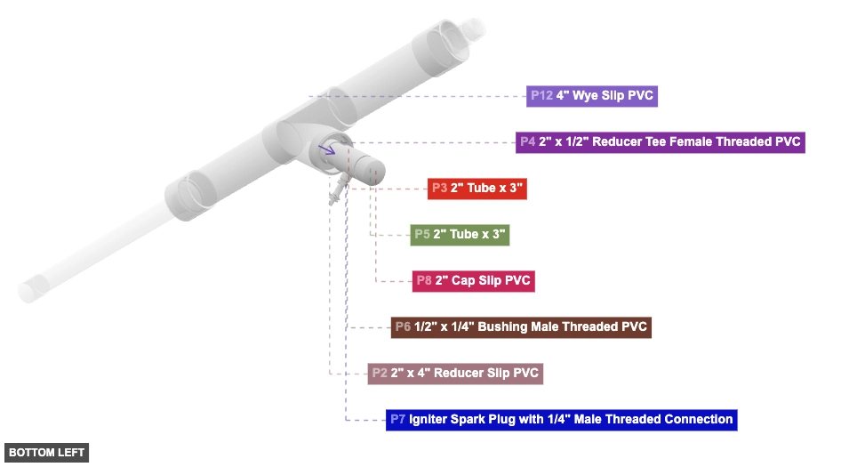
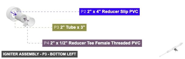
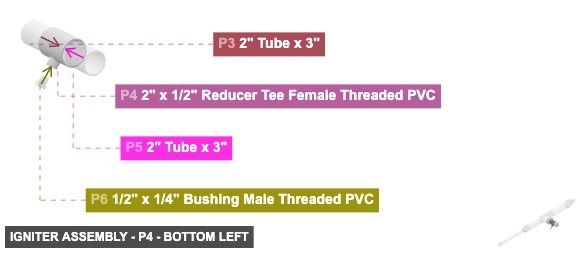
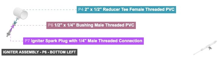
P2 (2" x 4" Reducer Slip PVC) - attach its 2" F SLIP #1 facing front-bottom to part 3's 2" M SLIP #2. Also, attach its 4" M SLIP #1 facing back-top to part 12's 4" F SLIP #2
P3 (2" Tube 3" length) - attach its 2" M SLIP #1 facing front-bottom to part 4's 2" F SLIP #1. Also, connect its 2" M SLIP #2 oriented back-top links with part 2's 2" F SLIP #1
P4 (2" x 1/2" Reducer Tee F Threaded PVC) - attach its 2" F SLIP #1 facing back-top to part 3's 2" M SLIP #1. Next, connect its 2" F SLIP #2 oriented front-bottom links with part 5's 2" M SLIP #2. Also, connect its 0.5" F Threaded #1 oriented back-bottom links with part 6's 0.5" M Threaded #1
P5 (2" Tube 3" length) - attach its 2" M SLIP #1 facing front-bottom to part 8's 2" F SLIP #1, also connect its 2" M SLIP #2 oriented back-top links with part 4's 2" F SLIP #2
P6 (0.5" x 1/4" Bushing M Threaded PVC) - connect its 0.5" M Threaded #1 oriented front-top links with part 4's 0.5" F Threaded #1. Next, connect its 0.25" F Threaded #1 oriented back-bottom links with part 7's 0.25" M Threaded #1
P7 (Igniter Spark Plug with M Threaded Connection) - its 0.25" M Threaded #1, which is front-top-facing, should connect to part 6's 0.25" F Threaded #1
P8 (2" Cap Slip PVC) - its 2" F SLIP #1, which is back-top-facing, should connect to part 5's 2" M SLIP #1
2" x 4" Reducer Slip PVCx 1 2" Tube x 3"x 2 2" x 1/2" Reducer Tee Female Threaded PVCx 1 1/2" x 1/4" Bushing Male Threaded PVCx 1 Igniter Spark Plug with 1/4" Male Threaded Connectionx 1 2" Cap Slip PVCx 1
Angle: bottom right
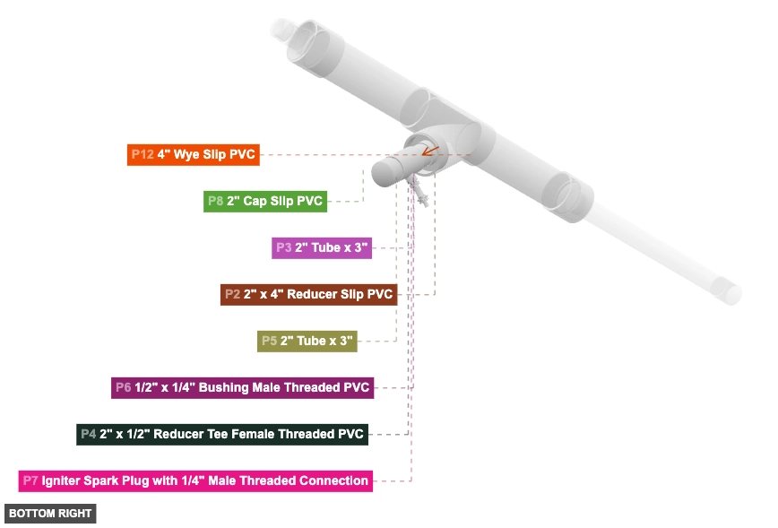
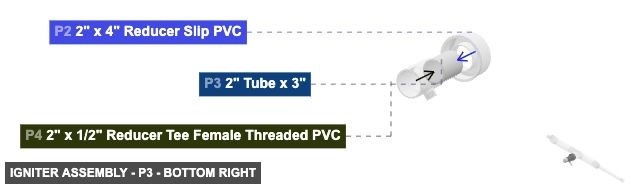
P2 (2" x 4" Reducer Slip PVC) - attach its 2" F SLIP #1 facing front-bottom to part 3's 2" M SLIP #2. Also, attach its 4" M SLIP #1 facing back-top to part 12's 4" F SLIP #2
P3 (2" Tube 3" length) - attach its 2" M SLIP #1 facing front-bottom to part 4's 2" F SLIP #1. Also, connect its 2" M SLIP #2 oriented back-top links with part 2's 2" F SLIP #1
P4 (2" x 1/2" Reducer Tee F Threaded PVC) - attach its 2" F SLIP #1 facing back-top to part 3's 2" M SLIP #1. Next, connect its 2" F SLIP #2 oriented front-bottom links with part 5's 2" M SLIP #2. Also, connect its 0.5" F Threaded #1 oriented back-bottom links with part 6's 0.5" M Threaded #1
P5 (2" Tube 3" length) - attach its 2" M SLIP #1 facing front-bottom to part 8's 2" F SLIP #1, also connect its 2" M SLIP #2 oriented back-top links with part 4's 2" F SLIP #2
P6 (0.5" x 1/4" Bushing M Threaded PVC) - connect its 0.5" M Threaded #1 oriented front-top links with part 4's 0.5" F Threaded #1. Next, connect its 0.25" F Threaded #1 oriented back-bottom links with part 7's 0.25" M Threaded #1
P7 (Igniter Spark Plug with M Threaded Connection) - its 0.25" M Threaded #1, which is front-top-facing, should connect to part 6's 0.25" F Threaded #1
P8 (2" Cap Slip PVC) - its 2" F SLIP #1, which is back-top-facing, should connect to part 5's 2" M SLIP #1
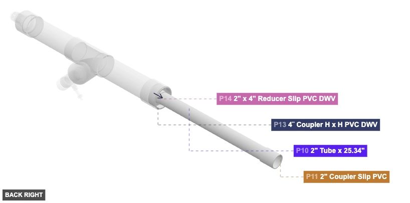
2" x 4" Reducer Slip PVCx 1 2" Tube x 3"x 2 2" x 1/2" Reducer Tee Female Threaded PVCx 1 1/2" x 1/4" Bushing Male Threaded PVCx 1 Igniter Spark Plug with 1/4" Male Threaded Connectionx 1 2" Cap Slip PVCx 1 Attaching: Barrel Assembly
Creates the main barrel tube with its connecting fittings.
The completed Barrel Assembly connects via P14's 4" Male SLIP (facing front) to the Main Body Assembly (P13).
Attaching: Muzzle Assembly
Creates the muzzle end cap/fitting for the combustion chamber side.
The completed Muzzle Assembly connects via P16's 4" Male SLIP (facing back) to the Main Body Assembly (P15).
Attaching: Main Body Assembly
Connects the main structural tubes and integrates the Igniter, Barrel, and Muzzle sub-assemblies.
Connect P12's 4" Female SLIP (facing front-bottom) to the Igniter Assembly (P2's 4" Male SLIP). Connect P13's 4" DWV Female connection (facing back) to the Barrel Assembly (P14's 4" Male SLIP). Connect P15's 4" DWV Female connection (facing front) to the Muzzle Assembly (P16's 4" Male SLIP).
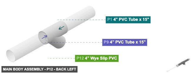
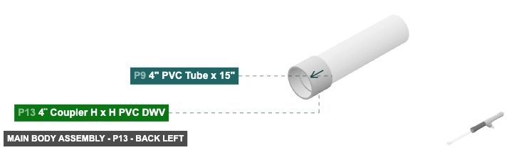
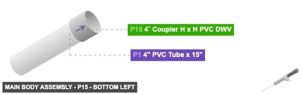
Angle: back left
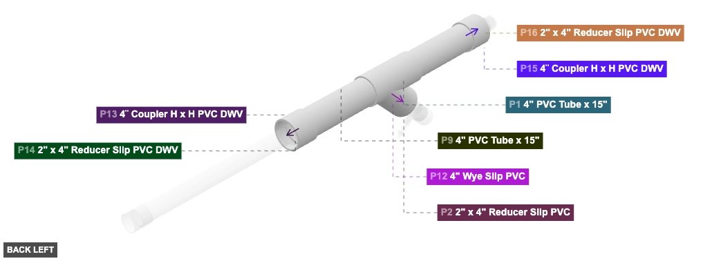
P1 (4" PVC Tube 15" length) - connect its 4" M SLIP #1 oriented back links with part 12's 4" F SLIP #1. After that, its 4" M SLIP #2, which is front-facing, should connect to part 15's 4" DWV F #1
P9 (4" PVC Tube 15" length) - attach its 4" M SLIP #1 facing back to part 13's 4" DWV F #1. Also, connect its 4" M SLIP #2 oriented front links with part 12's 4" F SLIP #3
P12 (4" Wye Slip PVC) - its 4" F SLIP #1, which is front-facing, should connect to part 1's 4" M SLIP #1, then attach its 4" F SLIP #2 facing front-bottom to part 2's 4" M SLIP #1, also connect its 4" F SLIP #3 oriented back links with part 9's 4" M SLIP #2
P13 (4¨ Coupler H x H PVC DWV) - attach its 4" DWV F #1 facing front to part 9's 4" M SLIP #1. Additionally, connect its 4" DWV F #2 oriented back links with part 14's 4" M SLIP #1
P15 (4¨ Coupler H x H PVC DWV) - connect its 4" DWV F #1 oriented back links with part 1's 4" M SLIP #2, also attach its 4" DWV F #2 facing front to part 16's 4" M SLIP #1
4" PVC Tube x 15"x 2 4" Wye Slip PVCx 1 4¨ Coupler H x H PVC DWVx 2
Angle: back right
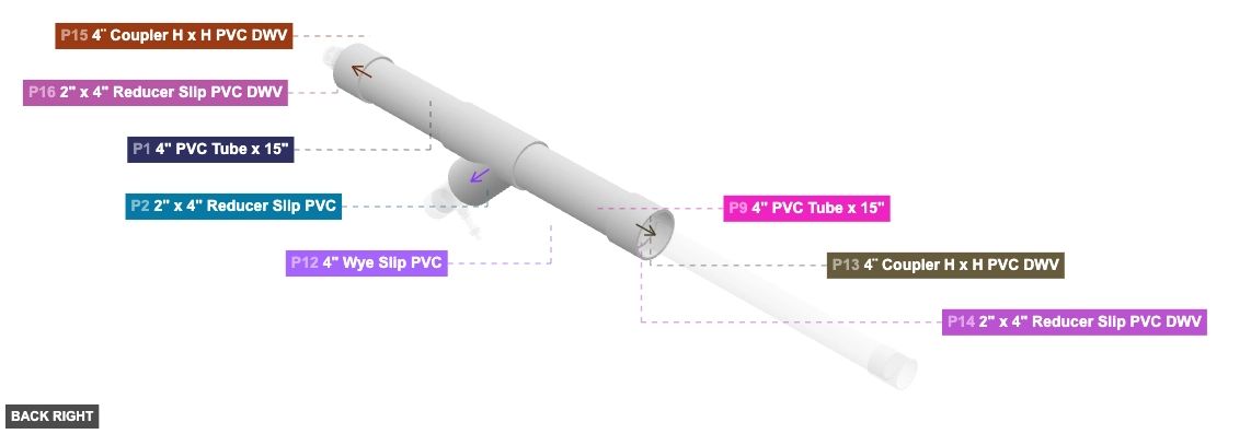
P1 (4" PVC Tube 15" length) - connect its 4" M SLIP #1 oriented back links with part 12's 4" F SLIP #1. After that, its 4" M SLIP #2, which is front-facing, should connect to part 15's 4" DWV F #1
P9 (4" PVC Tube 15" length) - attach its 4" M SLIP #1 facing back to part 13's 4" DWV F #1. Also, connect its 4" M SLIP #2 oriented front links with part 12's 4" F SLIP #3
P12 (4" Wye Slip PVC) - its 4" F SLIP #1, which is front-facing, should connect to part 1's 4" M SLIP #1, then attach its 4" F SLIP #2 facing front-bottom to part 2's 4" M SLIP #1, also connect its 4" F SLIP #3 oriented back links with part 9's 4" M SLIP #2
P13 (4¨ Coupler H x H PVC DWV) - attach its 4" DWV F #1 facing front to part 9's 4" M SLIP #1. Additionally, connect its 4" DWV F #2 oriented back links with part 14's 4" M SLIP #1
P15 (4¨ Coupler H x H PVC DWV) - connect its 4" DWV F #1 oriented back links with part 1's 4" M SLIP #2, also attach its 4" DWV F #2 facing front to part 16's 4" M SLIP #1
4" PVC Tube x 15"x 2 4" Wye Slip PVCx 1 4¨ Coupler H x H PVC DWVx 2
Angle: front left
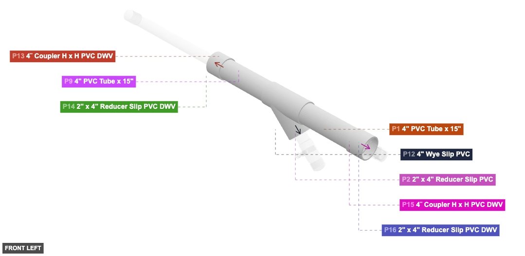
P1 (4" PVC Tube 15" length) - connect its 4" M SLIP #1 oriented back links with part 12's 4" F SLIP #1. After that, its 4" M SLIP #2, which is front-facing, should connect to part 15's 4" DWV F #1
P9 (4" PVC Tube 15" length) - attach its 4" M SLIP #1 facing back to part 13's 4" DWV F #1. Also, connect its 4" M SLIP #2 oriented front links with part 12's 4" F SLIP #3
P12 (4" Wye Slip PVC) - its 4" F SLIP #1, which is front-facing, should connect to part 1's 4" M SLIP #1, then attach its 4" F SLIP #2 facing front-bottom to part 2's 4" M SLIP #1, also connect its 4" F SLIP #3 oriented back links with part 9's 4" M SLIP #2
P13 (4¨ Coupler H x H PVC DWV) - attach its 4" DWV F #1 facing front to part 9's 4" M SLIP #1. Additionally, connect its 4" DWV F #2 oriented back links with part 14's 4" M SLIP #1
P15 (4¨ Coupler H x H PVC DWV) - connect its 4" DWV F #1 oriented back links with part 1's 4" M SLIP #2, also attach its 4" DWV F #2 facing front to part 16's 4" M SLIP #1
4" PVC Tube x 15"x 2 4" Wye Slip PVCx 1 4¨ Coupler H x H PVC DWVx 2
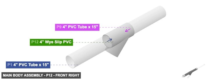
Angle: front right
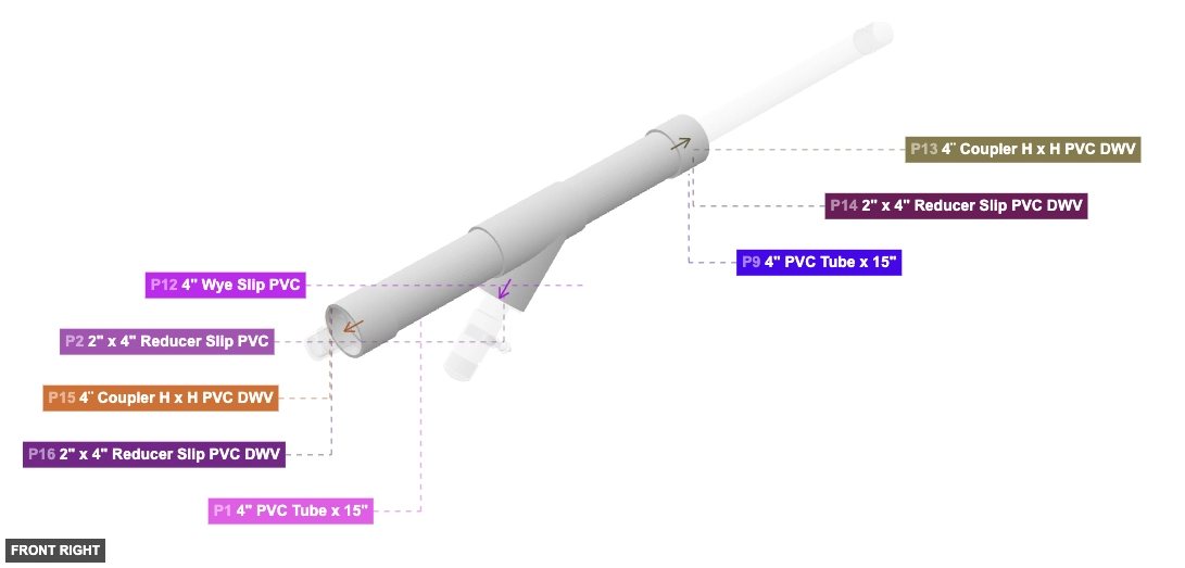
P1 (4" PVC Tube 15" length) - connect its 4" M SLIP #1 oriented back links with part 12's 4" F SLIP #1. After that, its 4" M SLIP #2, which is front-facing, should connect to part 15's 4" DWV F #1
P9 (4" PVC Tube 15" length) - attach its 4" M SLIP #1 facing back to part 13's 4" DWV F #1. Also, connect its 4" M SLIP #2 oriented front links with part 12's 4" F SLIP #3
P12 (4" Wye Slip PVC) - its 4" F SLIP #1, which is front-facing, should connect to part 1's 4" M SLIP #1, then attach its 4" F SLIP #2 facing front-bottom to part 2's 4" M SLIP #1, also connect its 4" F SLIP #3 oriented back links with part 9's 4" M SLIP #2
P13 (4¨ Coupler H x H PVC DWV) - attach its 4" DWV F #1 facing front to part 9's 4" M SLIP #1. Additionally, connect its 4" DWV F #2 oriented back links with part 14's 4" M SLIP #1
P15 (4¨ Coupler H x H PVC DWV) - connect its 4" DWV F #1 oriented back links with part 1's 4" M SLIP #2, also attach its 4" DWV F #2 facing front to part 16's 4" M SLIP #1
4" PVC Tube x 15"x 2 4" Wye Slip PVCx 1 4¨ Coupler H x H PVC DWVx 2
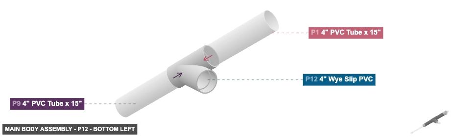
Angle: bottom left
P1 (4" PVC Tube 15" length) - connect its 4" M SLIP #1 oriented back links with part 12's 4" F SLIP #1. After that, its 4" M SLIP #2, which is front-facing, should connect to part 15's 4" DWV F #1
P9 (4" PVC Tube 15" length) - attach its 4" M SLIP #1 facing back to part 13's 4" DWV F #1. Also, connect its 4" M SLIP #2 oriented front links with part 12's 4" F SLIP #3
P12 (4" Wye Slip PVC) - its 4" F SLIP #1, which is front-facing, should connect to part 1's 4" M SLIP #1, then attach its 4" F SLIP #2 facing front-bottom to part 2's 4" M SLIP #1, also connect its 4" F SLIP #3 oriented back links with part 9's 4" M SLIP #2
P13 (4¨ Coupler H x H PVC DWV) - attach its 4" DWV F #1 facing front to part 9's 4" M SLIP #1. Additionally, connect its 4" DWV F #2 oriented back links with part 14's 4" M SLIP #1
P15 (4¨ Coupler H x H PVC DWV) - connect its 4" DWV F #1 oriented back links with part 1's 4" M SLIP #2, also attach its 4" DWV F #2 facing front to part 16's 4" M SLIP #1
4" PVC Tube x 15"x 2 4" Wye Slip PVCx 1 4¨ Coupler H x H PVC DWVx 2
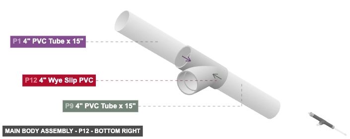
Angle: bottom right
P1 (4" PVC Tube 15" length) - connect its 4" M SLIP #1 oriented back links with part 12's 4" F SLIP #1. After that, its 4" M SLIP #2, which is front-facing, should connect to part 15's 4" DWV F #1
P9 (4" PVC Tube 15" length) - attach its 4" M SLIP #1 facing back to part 13's 4" DWV F #1. Also, connect its 4" M SLIP #2 oriented front links with part 12's 4" F SLIP #3
P12 (4" Wye Slip PVC) - its 4" F SLIP #1, which is front-facing, should connect to part 1's 4" M SLIP #1, then attach its 4" F SLIP #2 facing front-bottom to part 2's 4" M SLIP #1, also connect its 4" F SLIP #3 oriented back links with part 9's 4" M SLIP #2
P13 (4¨ Coupler H x H PVC DWV) - attach its 4" DWV F #1 facing front to part 9's 4" M SLIP #1. Additionally, connect its 4" DWV F #2 oriented back links with part 14's 4" M SLIP #1
P15 (4¨ Coupler H x H PVC DWV) - connect its 4" DWV F #1 oriented back links with part 1's 4" M SLIP #2, also attach its 4" DWV F #2 facing front to part 16's 4" M SLIP #1
4" PVC Tube x 15"x 2 4" Wye Slip PVCx 1 4¨ Coupler H x H PVC DWVx 2