Ram Pump - Comprehensive Assembly Plan And Visual Guide
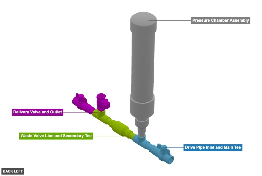
A water pump constructed primarily from PVC pipes and fittings, featuring a main T-junction, a vertical pressure chamber, a waste valve line with a check valve, and a delivery line with another check valve and ball valve. - Ram Pump
Phase 1: Group Overview
Angle: back left

Drive Pipe Inlet and Main Tee
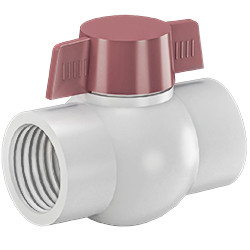 1" Ball Valve Threaded PVCx 1
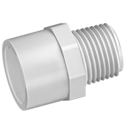 1" Adapter Male Threaded PVCx 1
 1" Tube x 3"x 1
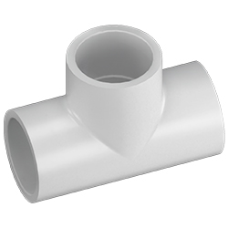 1" Tee Female Slip PVCx 1
Pressure Chamber Assembly
1" Tube x 3"x 1 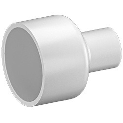 1" x 2" Reducer Slip PVCx 1
 2" Tube x 3"x 1
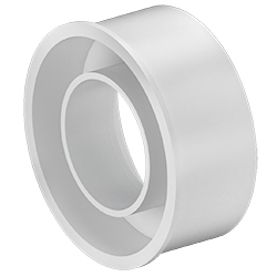 2" x 4" Reducer Slip PVCx 1
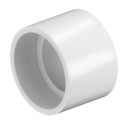 4¨ Coupler H x H PVC DWVx 1
 4" PVC PVC DWV x 18.5"x 1
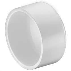 4" Cap Slip PVC DWVx 1
Waste Valve Line and Secondary Tee
1" Tube x 3"x 2 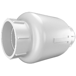 1" Check Valve Slip PVCx 1
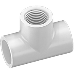 1" Tee Female Threaded PVCx 1
Delivery Valve and Outlet
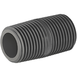 1" x 2" Nipple PVCx 1
1" Tube x 3"x 1 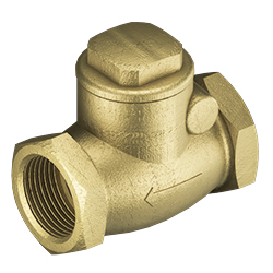 1” Swing Check Valve Brassx 1
1" Adapter Male Threaded PVCx 1 1" Ball Valve Threaded PVCx 1
Angle: back right
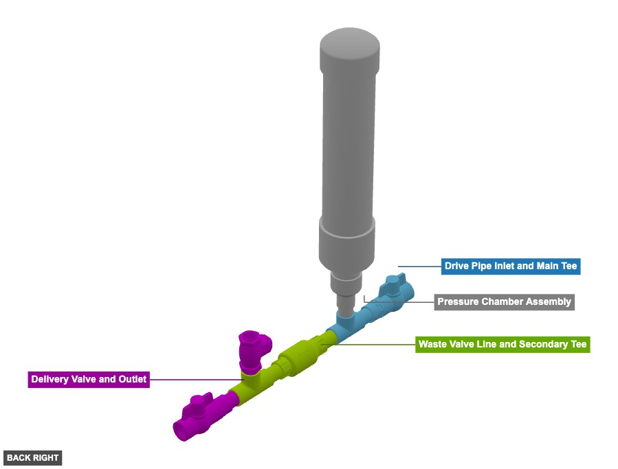
Drive Pipe Inlet and Main Tee
1" Ball Valve Threaded PVCx 1 1" Adapter Male Threaded PVCx 1 1" Tube x 3"x 1 1" Tee Female Slip PVCx 1 Pressure Chamber Assembly
1" Tube x 3"x 1 1" x 2" Reducer Slip PVCx 1 2" Tube x 3"x 1 2" x 4" Reducer Slip PVCx 1 4¨ Coupler H x H PVC DWVx 1 4" PVC PVC DWV x 18.5"x 1 4" Cap Slip PVC DWVx 1 Waste Valve Line and Secondary Tee
1" Tube x 3"x 2 1" Check Valve Slip PVCx 1 1" Tee Female Threaded PVCx 1 Delivery Valve and Outlet
1" x 2" Nipple PVCx 1 1" Tube x 3"x 1 1” Swing Check Valve Brassx 1 1" Adapter Male Threaded PVCx 1 1" Ball Valve Threaded PVCx 1
Angle: front left
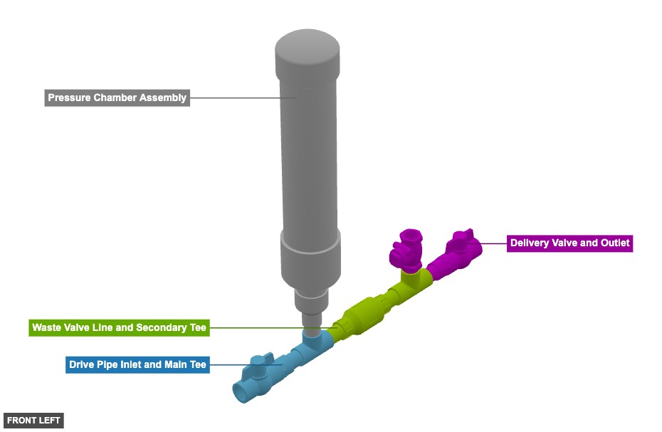
Drive Pipe Inlet and Main Tee
1" Ball Valve Threaded PVCx 1 1" Adapter Male Threaded PVCx 1 1" Tube x 3"x 1 1" Tee Female Slip PVCx 1 Pressure Chamber Assembly
1" Tube x 3"x 1 1" x 2" Reducer Slip PVCx 1 2" Tube x 3"x 1 2" x 4" Reducer Slip PVCx 1 4¨ Coupler H x H PVC DWVx 1 4" PVC PVC DWV x 18.5"x 1 4" Cap Slip PVC DWVx 1 Waste Valve Line and Secondary Tee
1" Tube x 3"x 2 1" Check Valve Slip PVCx 1 1" Tee Female Threaded PVCx 1 Delivery Valve and Outlet
1" x 2" Nipple PVCx 1 1" Tube x 3"x 1 1” Swing Check Valve Brassx 1 1" Adapter Male Threaded PVCx 1 1" Ball Valve Threaded PVCx 1
Angle: front right
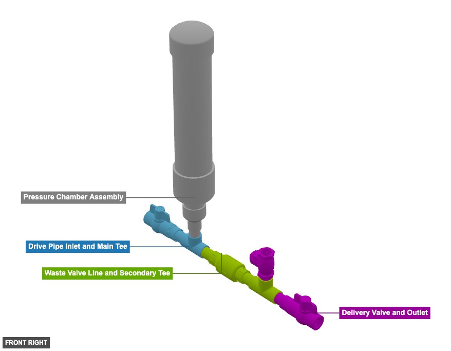
Drive Pipe Inlet and Main Tee
1" Ball Valve Threaded PVCx 1 1" Adapter Male Threaded PVCx 1 1" Tube x 3"x 1 1" Tee Female Slip PVCx 1 Pressure Chamber Assembly
1" Tube x 3"x 1 1" x 2" Reducer Slip PVCx 1 2" Tube x 3"x 1 2" x 4" Reducer Slip PVCx 1 4¨ Coupler H x H PVC DWVx 1 4" PVC PVC DWV x 18.5"x 1 4" Cap Slip PVC DWVx 1 Waste Valve Line and Secondary Tee
1" Tube x 3"x 2 1" Check Valve Slip PVCx 1 1" Tee Female Threaded PVCx 1 Delivery Valve and Outlet
1" x 2" Nipple PVCx 1 1" Tube x 3"x 1 1” Swing Check Valve Brassx 1 1" Adapter Male Threaded PVCx 1 1" Ball Valve Threaded PVCx 1
Angle: bottom left
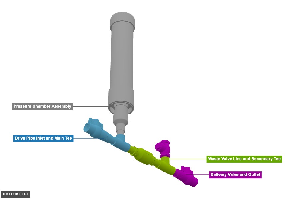
Drive Pipe Inlet and Main Tee
1" Ball Valve Threaded PVCx 1 1" Adapter Male Threaded PVCx 1 1" Tube x 3"x 1 1" Tee Female Slip PVCx 1 Pressure Chamber Assembly
1" Tube x 3"x 1 1" x 2" Reducer Slip PVCx 1 2" Tube x 3"x 1 2" x 4" Reducer Slip PVCx 1 4¨ Coupler H x H PVC DWVx 1 4" PVC PVC DWV x 18.5"x 1 4" Cap Slip PVC DWVx 1 Waste Valve Line and Secondary Tee
1" Tube x 3"x 2 1" Check Valve Slip PVCx 1 1" Tee Female Threaded PVCx 1 Delivery Valve and Outlet
1" x 2" Nipple PVCx 1 1" Tube x 3"x 1 1” Swing Check Valve Brassx 1 1" Adapter Male Threaded PVCx 1 1" Ball Valve Threaded PVCx 1
Angle: bottom right
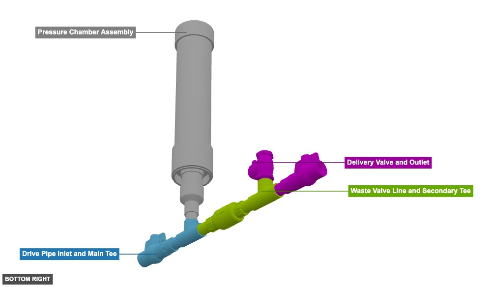
Drive Pipe Inlet and Main Tee
1" Ball Valve Threaded PVCx 1 1" Adapter Male Threaded PVCx 1 1" Tube x 3"x 1 1" Tee Female Slip PVCx 1 Pressure Chamber Assembly
1" Tube x 3"x 1 1" x 2" Reducer Slip PVCx 1 2" Tube x 3"x 1 2" x 4" Reducer Slip PVCx 1 4¨ Coupler H x H PVC DWVx 1 4" PVC PVC DWV x 18.5"x 1 4" Cap Slip PVC DWVx 1 Waste Valve Line and Secondary Tee
1" Tube x 3"x 2 1" Check Valve Slip PVCx 1 1" Tee Female Threaded PVCx 1 Delivery Valve and Outlet
1" x 2" Nipple PVCx 1 1" Tube x 3"x 1 1” Swing Check Valve Brassx 1 1" Adapter Male Threaded PVCx 1 1" Ball Valve Threaded PVCx 1 Phase 2: Individual Group Assembly
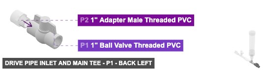
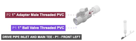
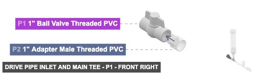
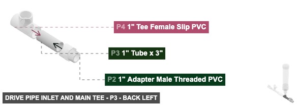
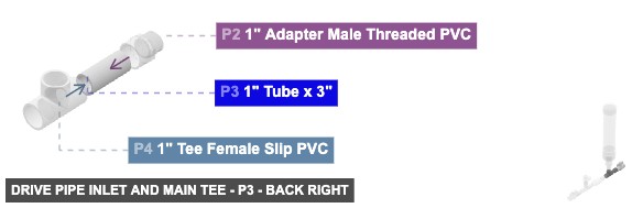
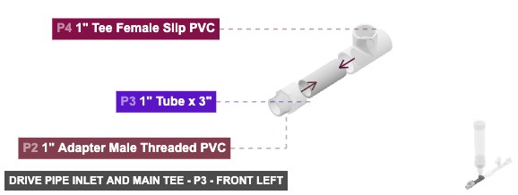
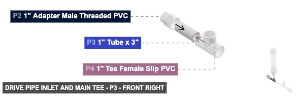
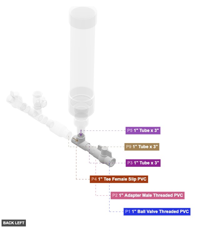
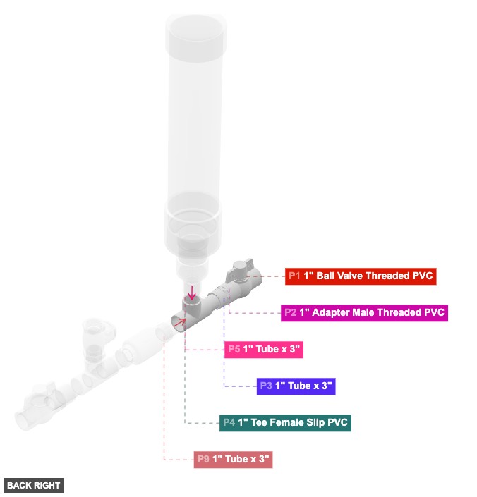
Group: Drive Pipe Inlet and Main Tee
Forms the initial water intake path and the central connection point (P4).
Connect P1 (1" Ball Valve) 1" Female Threaded facing right to P2 (1" Adapter) 1" Male Threaded. Connect P2 1" Female SLIP facing right to P3 (1" Tube) 1" Male SLIP. Connect P3 1" Male SLIP facing right to P4 (1" Tee) left 1" Female SLIP.
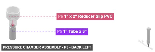
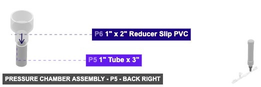
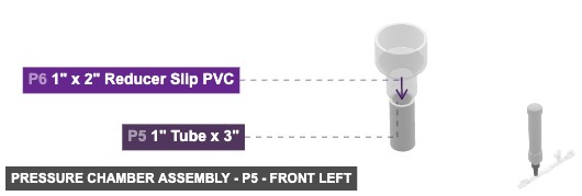
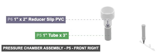
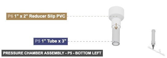
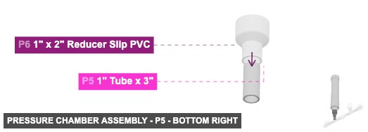
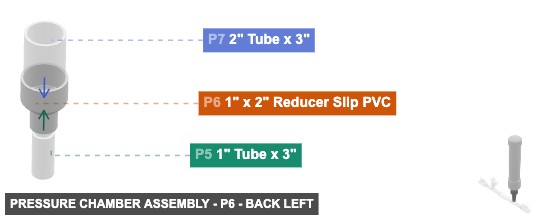
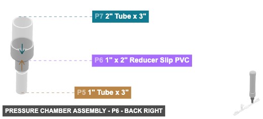
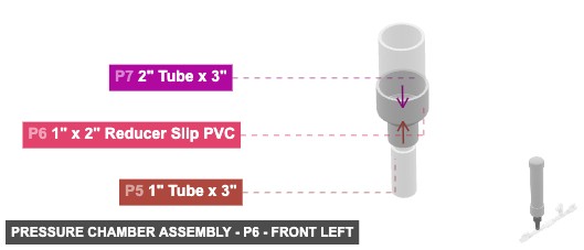
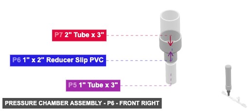
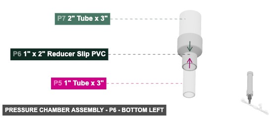
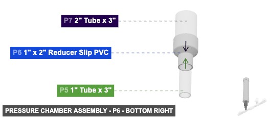
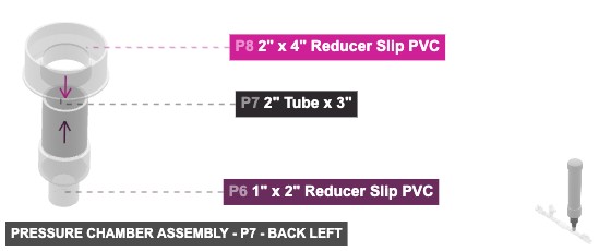
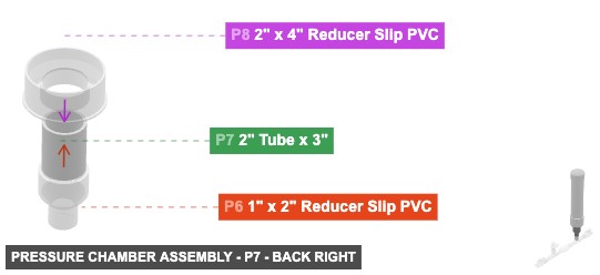
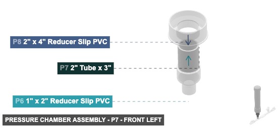
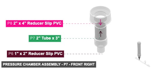
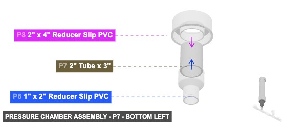
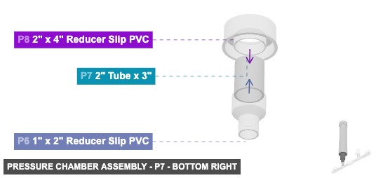
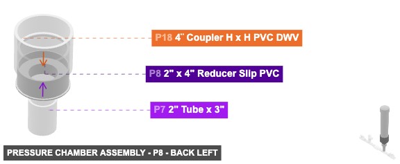
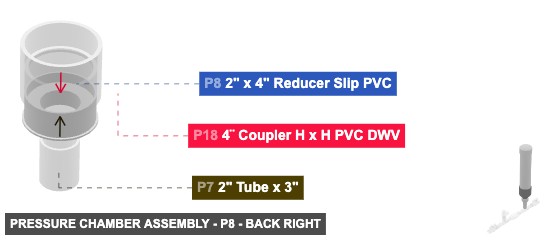
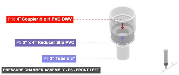
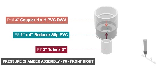
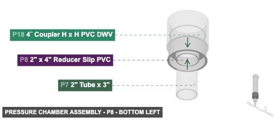
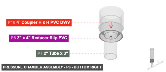
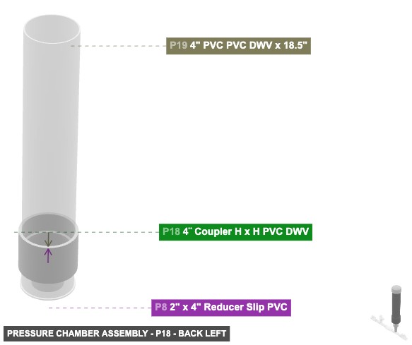
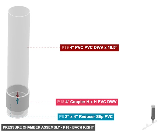
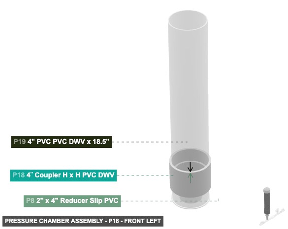
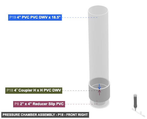
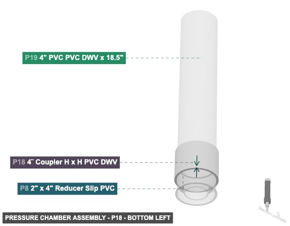
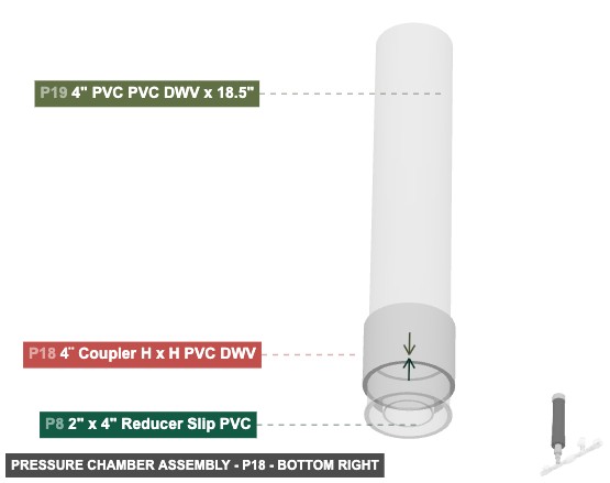
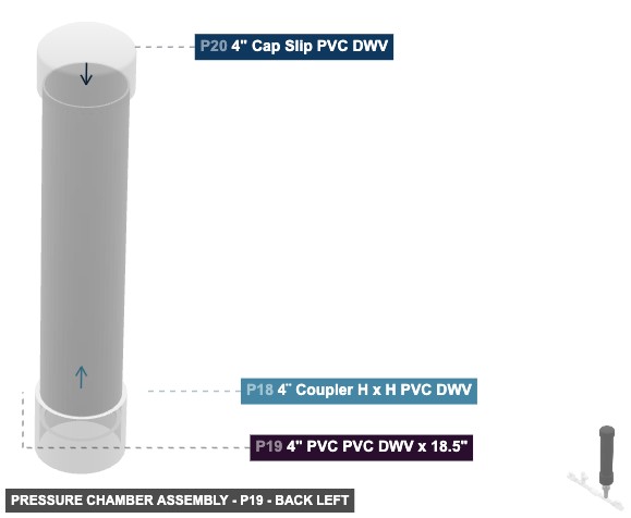
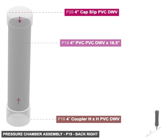
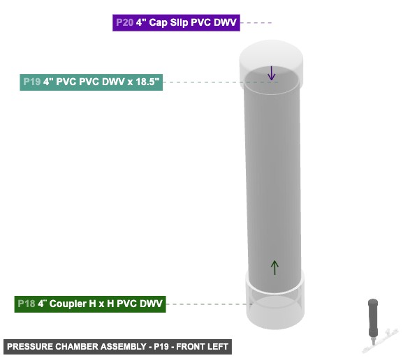
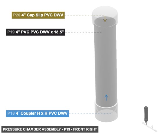
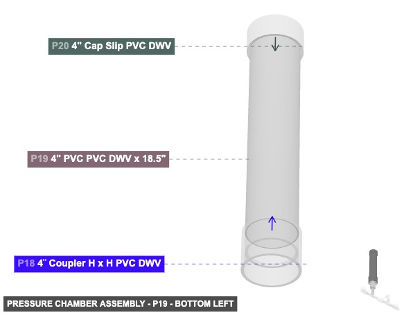
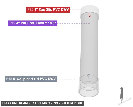
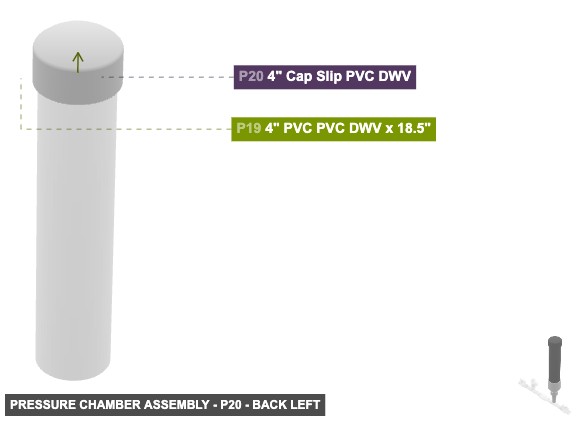
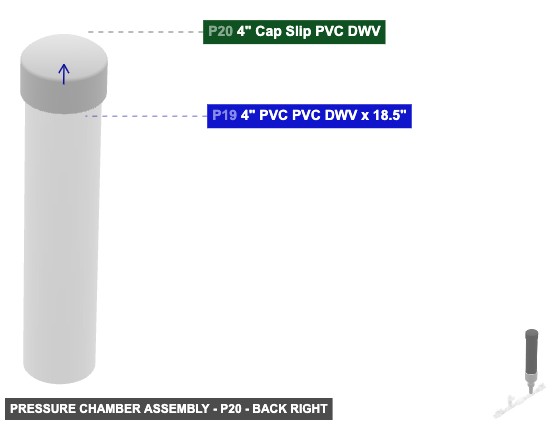
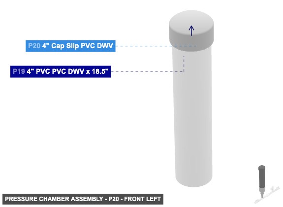
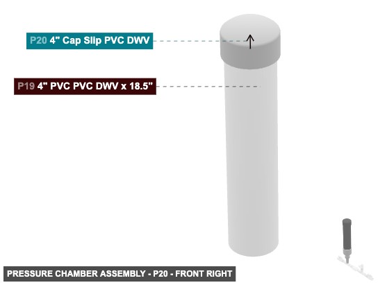
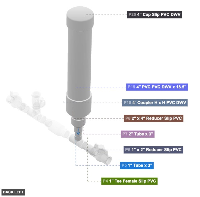
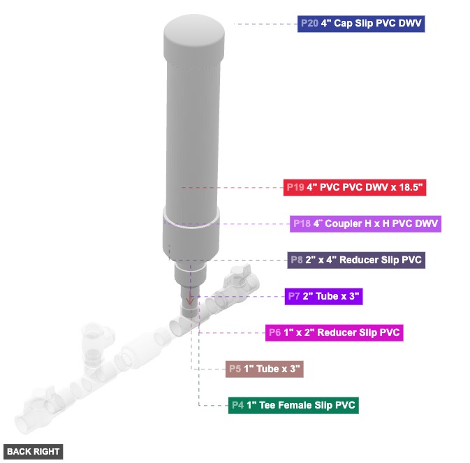
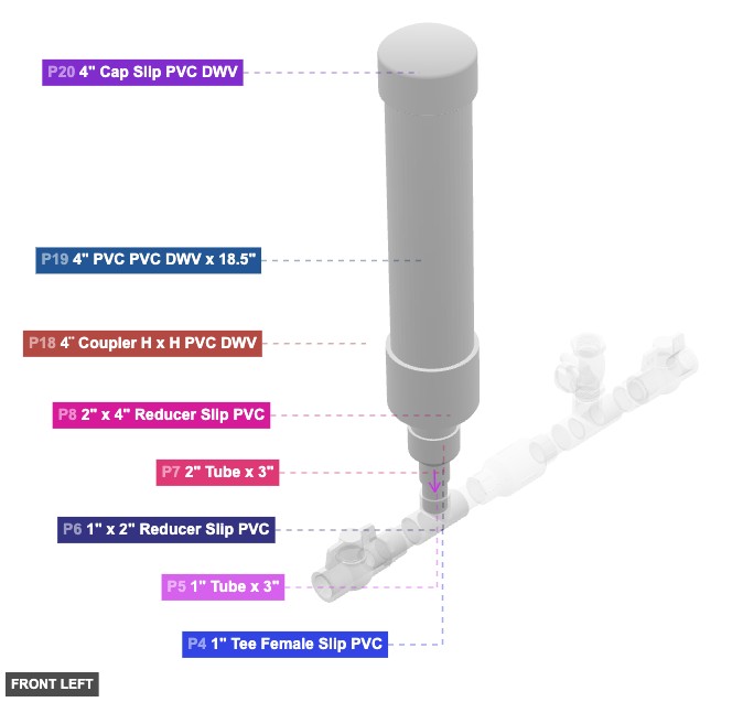
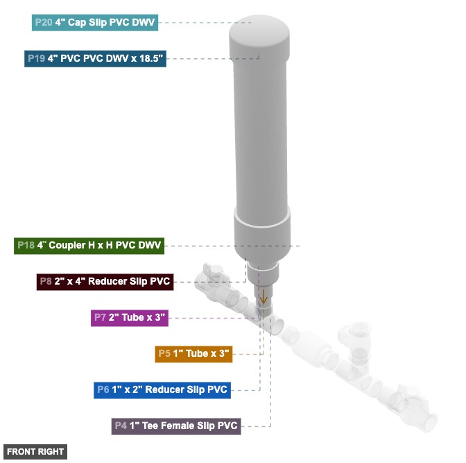
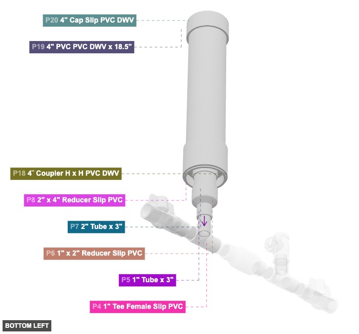
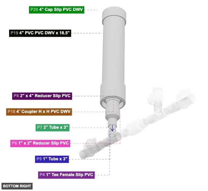
Group: Pressure Chamber Assembly
Creates the vertical air pressure chamber required for the pump's operation.
Connect P5 (1" Tube) top 1" Male SLIP to P6 (1"x2" Reducer) 1" Female SLIP. Connect P6 2" Female SLIP to P7 (2" Tube) bottom 2" Male SLIP. Connect P7 top 2" Male SLIP to P8 (2"x4" Reducer) 2" Female SLIP. Connect P8 4" Male SLIP to P18 (4" Coupler) bottom 4" DWV Female. Connect P18 top 4" DWV Female to P19 (4" Tube) bottom 4" Male SLIP. Connect P19 top 4" Male SLIP to P20 (4" Cap) 4" Female SLIP.
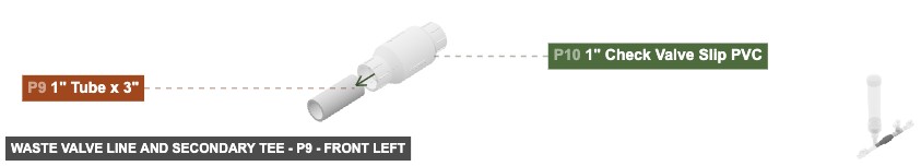
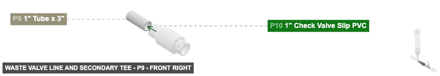
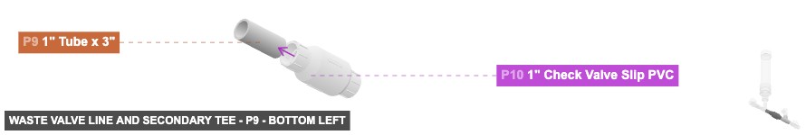
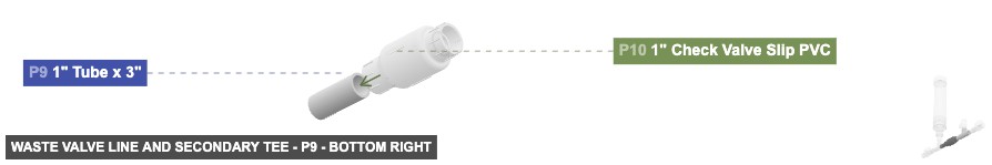
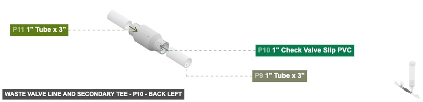
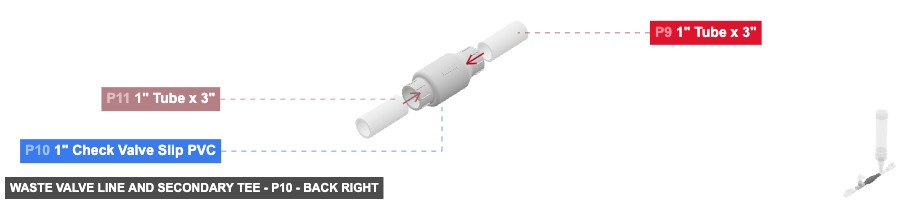
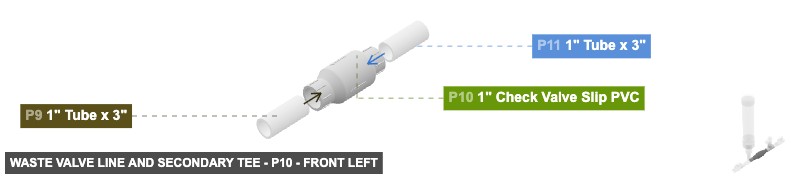
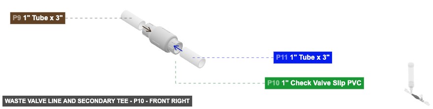
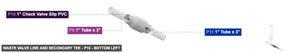
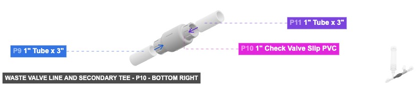
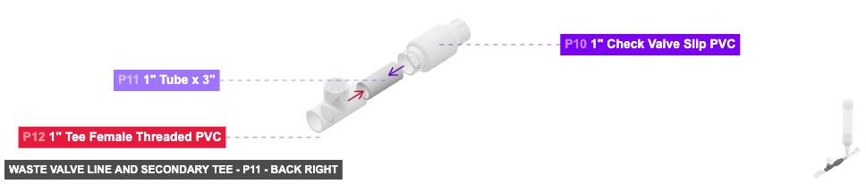
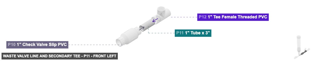
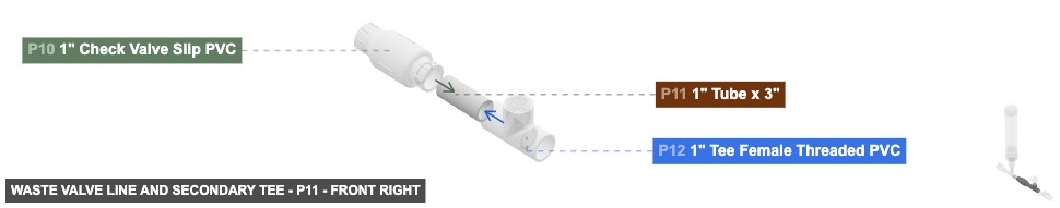
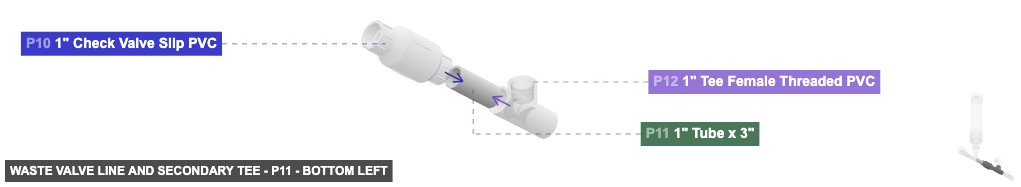
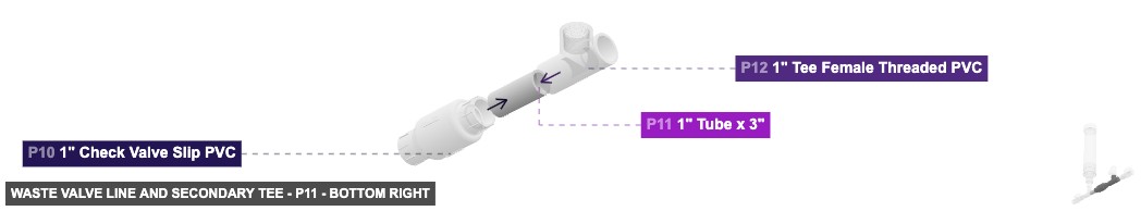
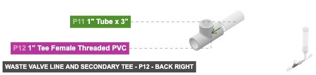
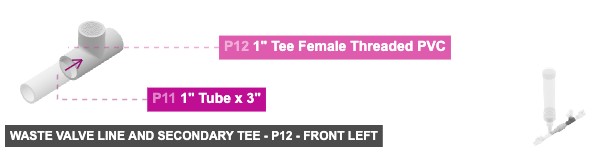
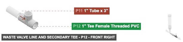
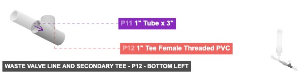
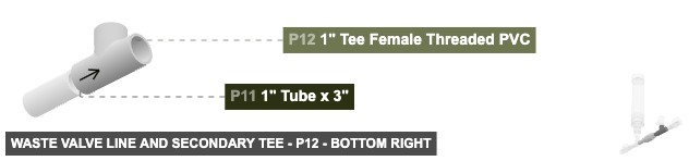
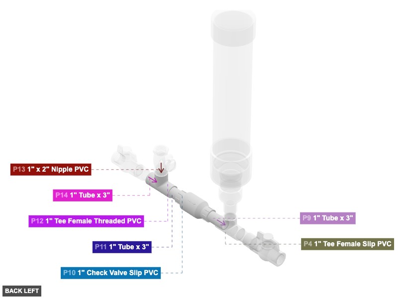
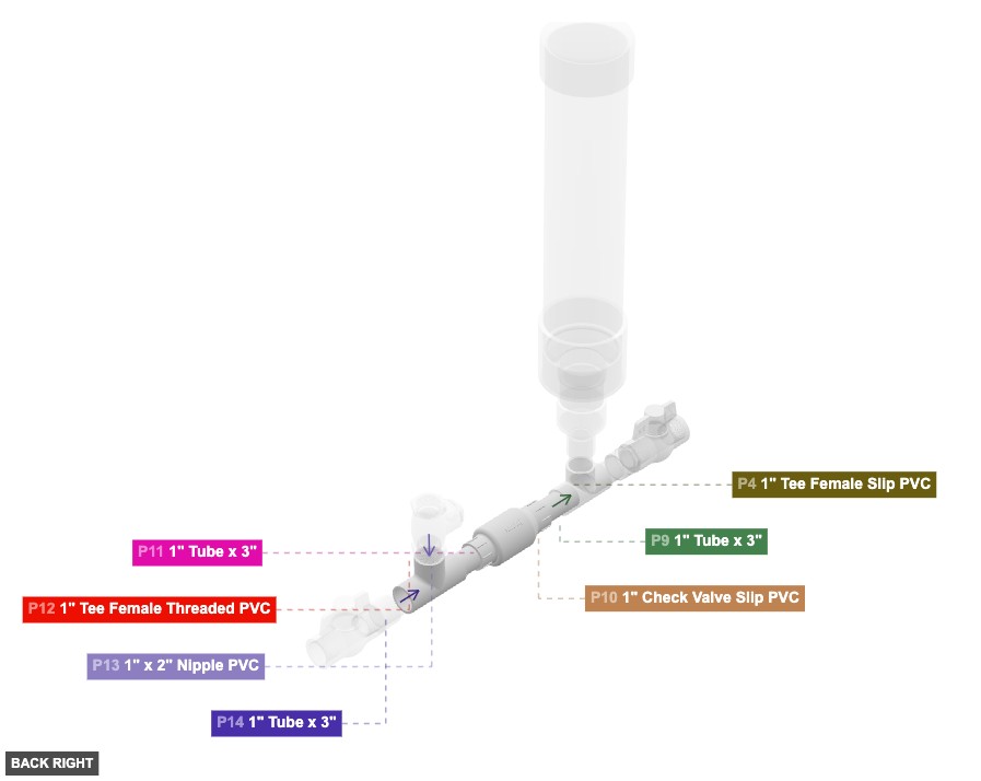
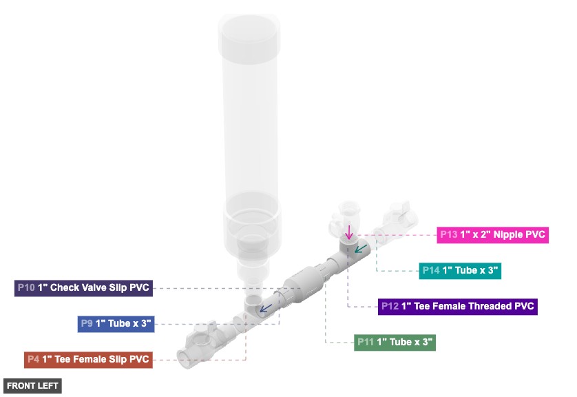
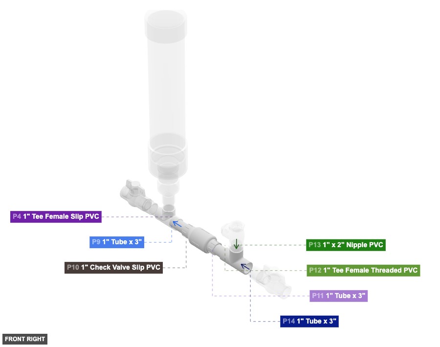
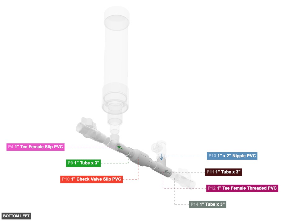
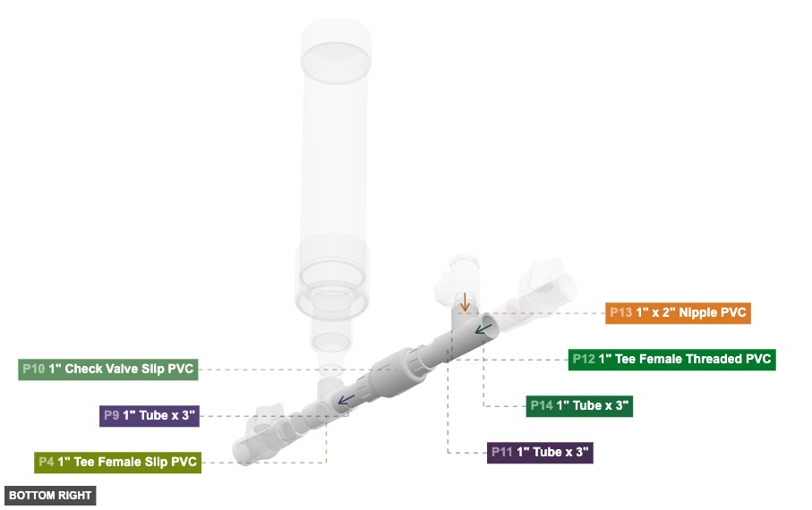
Group: Waste Valve Line and Secondary Tee
Forms the path for the waste valve (P10) and connects to the delivery line tee (P12).
Connect P9 (1" Tube) right 1" Male SLIP to P10 (1" Check Valve) left 1" Female SLIP. Connect P10 right 1" Female SLIP to P11 (1" Tube) left 1" Male SLIP. Connect P11 right 1" Male SLIP to P12 (1" Tee) left 1" Female SLIP.
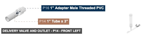
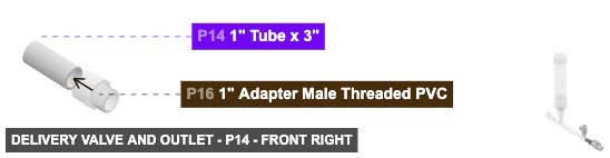
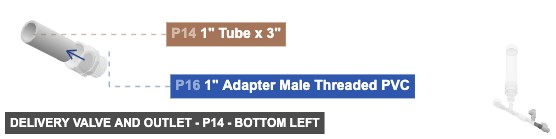
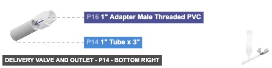
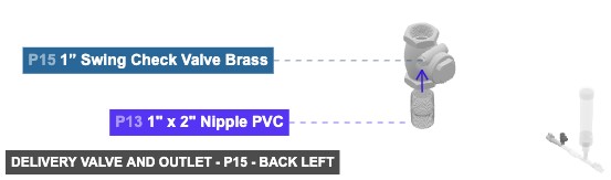
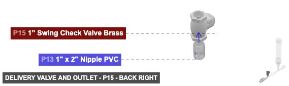
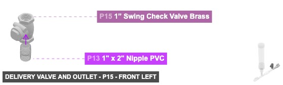
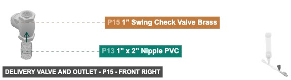
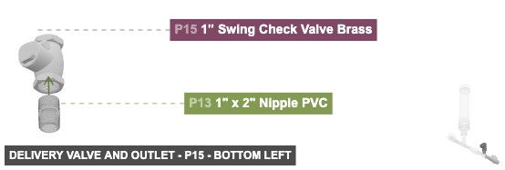
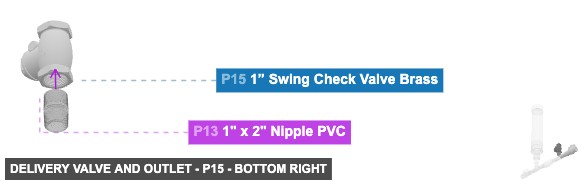
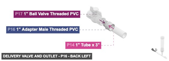
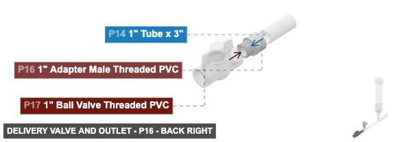
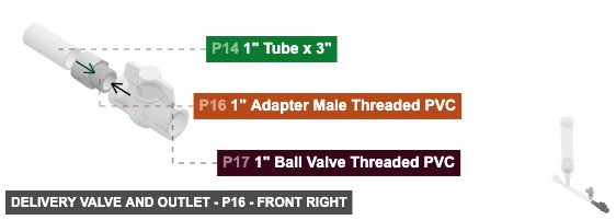
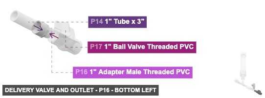
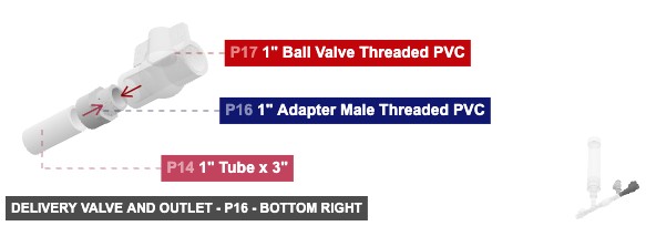
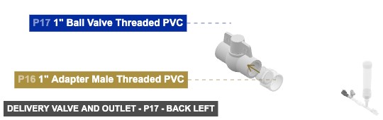
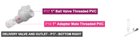
Group: Delivery Valve and Outlet
Forms the final delivery path for the pumped water, including the delivery check valve (P15) and outlet valve (P17).
Connect P13 (1"x2" Nipple) top 1" Male Threaded to P15 (1" Swing Check Valve) bottom 1" Female Threaded. Connect P14 (1" Tube) right 1" Male SLIP to P16 (1" Adapter) left 1" Female SLIP. Connect P16 right 1" Male Threaded to P17 (1" Ball Valve) left 1" Female Threaded.
Phase 3: Inter-Group Assembly
Attaching: Drive Pipe Inlet and Main Tee
Forms the initial water intake path and the central connection point (P4).
This group serves as the base. The Pressure Chamber (Group 2) connects to the top 1" Female SLIP of P4. The Waste Valve Line (Group 3) connects to the right 1" Female SLIP of P4.
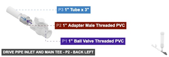
Angle: back left
P1 (1" Ball Valve Threaded PVC) - its 1" F Threaded #1, which is right-facing, should connect to part 2's 1" M Threaded #1, also its 1" F Threaded #2 should be directed left
P2 (1" Adapter M Threaded PVC) - its 1" M Threaded #1, which is left-facing, should connect to part 1's 1" F Threaded #1. Also, connect its 1" F SLIP #1 oriented right links with part 3's 1" M SLIP #2
P3 (1" Tube 3" length) - attach its 1" M SLIP #1 facing right to part 4's 1" F SLIP #1, plus connect its 1" M SLIP #2 oriented left links with part 2's 1" F SLIP #1
P4 (1" Tee F Slip PVC) - attach its 1" F SLIP #1 facing left to part 3's 1" M SLIP #1. Additionally, its 1" F SLIP #2, which is right-facing, should connect to part 9's 1" M SLIP #2, then connect its 1" F SLIP #3 oriented top links with part 5's 1" M SLIP #2
1" Ball Valve Threaded PVCx 1 1" Adapter Male Threaded PVCx 1 1" Tube x 3"x 1 1" Tee Female Slip PVCx 1
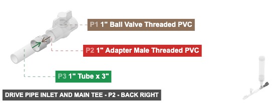
Angle: back right
P1 (1" Ball Valve Threaded PVC) - its 1" F Threaded #1, which is right-facing, should connect to part 2's 1" M Threaded #1, also its 1" F Threaded #2 should be directed left
P2 (1" Adapter M Threaded PVC) - its 1" M Threaded #1, which is left-facing, should connect to part 1's 1" F Threaded #1. Also, connect its 1" F SLIP #1 oriented right links with part 3's 1" M SLIP #2
P3 (1" Tube 3" length) - attach its 1" M SLIP #1 facing right to part 4's 1" F SLIP #1, plus connect its 1" M SLIP #2 oriented left links with part 2's 1" F SLIP #1
P4 (1" Tee F Slip PVC) - attach its 1" F SLIP #1 facing left to part 3's 1" M SLIP #1. Additionally, its 1" F SLIP #2, which is right-facing, should connect to part 9's 1" M SLIP #2, then connect its 1" F SLIP #3 oriented top links with part 5's 1" M SLIP #2
1" Ball Valve Threaded PVCx 1 1" Adapter Male Threaded PVCx 1 1" Tube x 3"x 1 1" Tee Female Slip PVCx 1
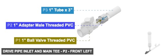
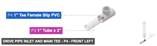
Angle: front left
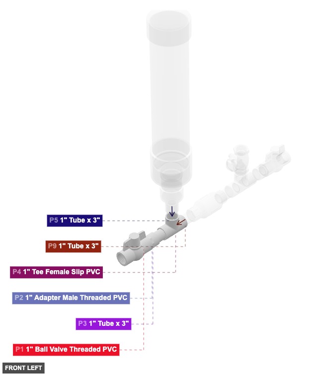
P1 (1" Ball Valve Threaded PVC) - its 1" F Threaded #1, which is right-facing, should connect to part 2's 1" M Threaded #1, also its 1" F Threaded #2 should be directed left
P2 (1" Adapter M Threaded PVC) - its 1" M Threaded #1, which is left-facing, should connect to part 1's 1" F Threaded #1. Also, connect its 1" F SLIP #1 oriented right links with part 3's 1" M SLIP #2
P3 (1" Tube 3" length) - attach its 1" M SLIP #1 facing right to part 4's 1" F SLIP #1, plus connect its 1" M SLIP #2 oriented left links with part 2's 1" F SLIP #1
P4 (1" Tee F Slip PVC) - attach its 1" F SLIP #1 facing left to part 3's 1" M SLIP #1. Additionally, its 1" F SLIP #2, which is right-facing, should connect to part 9's 1" M SLIP #2, then connect its 1" F SLIP #3 oriented top links with part 5's 1" M SLIP #2
1" Ball Valve Threaded PVCx 1 1" Adapter Male Threaded PVCx 1 1" Tube x 3"x 1 1" Tee Female Slip PVCx 1
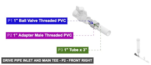
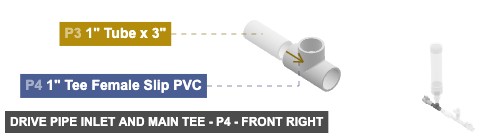
Angle: front right
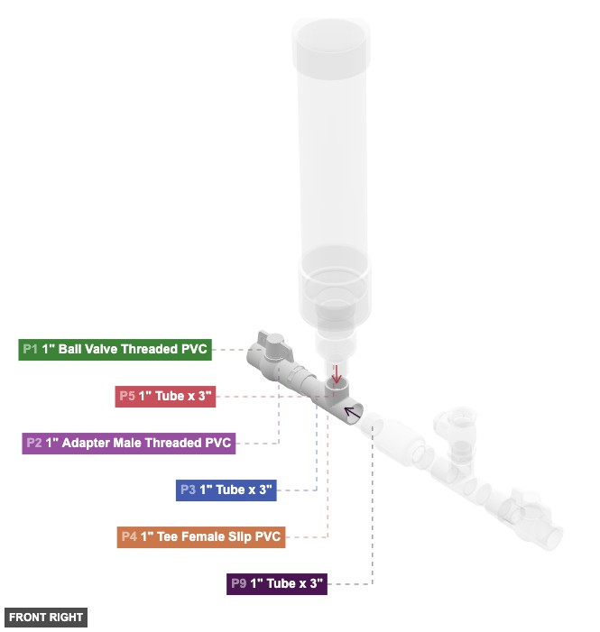
P1 (1" Ball Valve Threaded PVC) - its 1" F Threaded #1, which is right-facing, should connect to part 2's 1" M Threaded #1, also its 1" F Threaded #2 should be directed left
P2 (1" Adapter M Threaded PVC) - its 1" M Threaded #1, which is left-facing, should connect to part 1's 1" F Threaded #1. Also, connect its 1" F SLIP #1 oriented right links with part 3's 1" M SLIP #2
P3 (1" Tube 3" length) - attach its 1" M SLIP #1 facing right to part 4's 1" F SLIP #1, plus connect its 1" M SLIP #2 oriented left links with part 2's 1" F SLIP #1
P4 (1" Tee F Slip PVC) - attach its 1" F SLIP #1 facing left to part 3's 1" M SLIP #1. Additionally, its 1" F SLIP #2, which is right-facing, should connect to part 9's 1" M SLIP #2, then connect its 1" F SLIP #3 oriented top links with part 5's 1" M SLIP #2
1" Ball Valve Threaded PVCx 1 1" Adapter Male Threaded PVCx 1 1" Tube x 3"x 1 1" Tee Female Slip PVCx 1
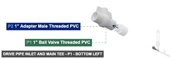
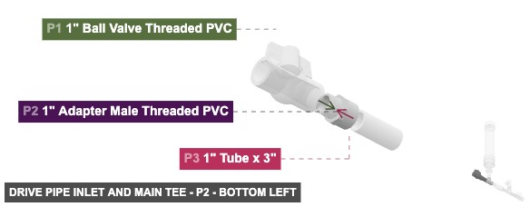
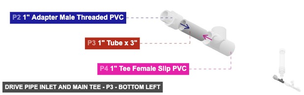
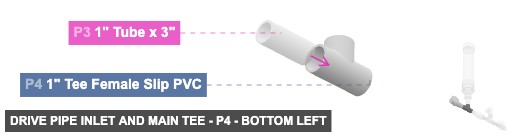
Angle: bottom left
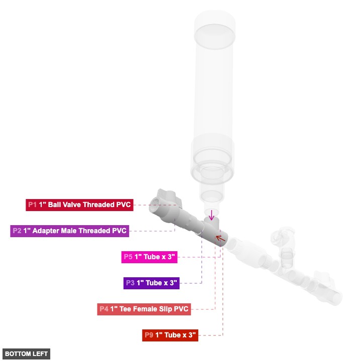
P1 (1" Ball Valve Threaded PVC) - its 1" F Threaded #1, which is right-facing, should connect to part 2's 1" M Threaded #1, also its 1" F Threaded #2 should be directed left
P2 (1" Adapter M Threaded PVC) - its 1" M Threaded #1, which is left-facing, should connect to part 1's 1" F Threaded #1. Also, connect its 1" F SLIP #1 oriented right links with part 3's 1" M SLIP #2
P3 (1" Tube 3" length) - attach its 1" M SLIP #1 facing right to part 4's 1" F SLIP #1, plus connect its 1" M SLIP #2 oriented left links with part 2's 1" F SLIP #1
P4 (1" Tee F Slip PVC) - attach its 1" F SLIP #1 facing left to part 3's 1" M SLIP #1. Additionally, its 1" F SLIP #2, which is right-facing, should connect to part 9's 1" M SLIP #2, then connect its 1" F SLIP #3 oriented top links with part 5's 1" M SLIP #2
1" Ball Valve Threaded PVCx 1 1" Adapter Male Threaded PVCx 1 1" Tube x 3"x 1 1" Tee Female Slip PVCx 1
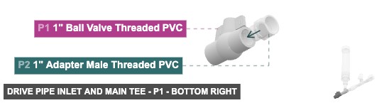
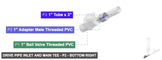
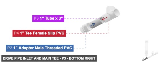
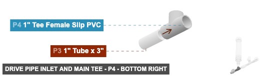
Angle: bottom right
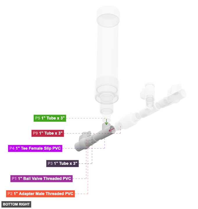
P1 (1" Ball Valve Threaded PVC) - its 1" F Threaded #1, which is right-facing, should connect to part 2's 1" M Threaded #1, also its 1" F Threaded #2 should be directed left
P2 (1" Adapter M Threaded PVC) - its 1" M Threaded #1, which is left-facing, should connect to part 1's 1" F Threaded #1. Also, connect its 1" F SLIP #1 oriented right links with part 3's 1" M SLIP #2
P3 (1" Tube 3" length) - attach its 1" M SLIP #1 facing right to part 4's 1" F SLIP #1, plus connect its 1" M SLIP #2 oriented left links with part 2's 1" F SLIP #1
P4 (1" Tee F Slip PVC) - attach its 1" F SLIP #1 facing left to part 3's 1" M SLIP #1. Additionally, its 1" F SLIP #2, which is right-facing, should connect to part 9's 1" M SLIP #2, then connect its 1" F SLIP #3 oriented top links with part 5's 1" M SLIP #2
1" Ball Valve Threaded PVCx 1 1" Adapter Male Threaded PVCx 1 1" Tube x 3"x 1 1" Tee Female Slip PVCx 1 Attaching: Pressure Chamber Assembly
Creates the vertical air pressure chamber required for the pump's operation.
Connect the bottom 1" Male SLIP of P5 to the top 1" Female SLIP of P4 in Group 1.
Angle: back left
P5 (1" Tube 3" length) - attach its 1" M SLIP #1 facing top to part 6's 1" F SLIP #1, also connect its 1" M SLIP #2 oriented bottom links with part 4's 1" F SLIP #3
P6 (1" x 2" Reducer Slip PVC) - attach its 1" F SLIP #1 facing bottom to part 5's 1" M SLIP #1. Also, connect its 2" F SLIP #1 oriented top links with part 7's 2" M SLIP #2
P7 (2" Tube 3" length) - its 2" M SLIP #1, which is top-facing, should connect to part 8's 2" F SLIP #1, also attach its 2" M SLIP #2 facing bottom to part 6's 2" F SLIP #1
P8 (2" x 4" Reducer Slip PVC) - connect its 2" F SLIP #1 oriented bottom links with part 7's 2" M SLIP #1, plus connect its 4" M SLIP #1 oriented top links with part 18's 4" DWV F #1
P18 (4¨ Coupler H x H PVC DWV) - attach its 4" DWV F #1 facing bottom to part 8's 4" M SLIP #1. Also, its 4" DWV F #2, which is top-facing, should connect to part 19's 4" M SLIP #2
P19 (4" PVC PVC DWV 18.5" length) - connect its 4" M SLIP #1 oriented top links with part 20's 4" F SLIP #1, and its 4" M SLIP #2, which is bottom-facing, should connect to part 18's 4" DWV F #2
P20 (4" Cap Slip PVC DWV) - its 4" F SLIP #1, which is bottom-facing, should connect to part 19's 4" M SLIP #1
1" Tube x 3"x 1 1" x 2" Reducer Slip PVCx 1 2" Tube x 3"x 1 2" x 4" Reducer Slip PVCx 1 4¨ Coupler H x H PVC DWVx 1 4" PVC PVC DWV x 18.5"x 1 4" Cap Slip PVC DWVx 1
Angle: back right
P5 (1" Tube 3" length) - attach its 1" M SLIP #1 facing top to part 6's 1" F SLIP #1, also connect its 1" M SLIP #2 oriented bottom links with part 4's 1" F SLIP #3
P6 (1" x 2" Reducer Slip PVC) - attach its 1" F SLIP #1 facing bottom to part 5's 1" M SLIP #1. Also, connect its 2" F SLIP #1 oriented top links with part 7's 2" M SLIP #2
P7 (2" Tube 3" length) - its 2" M SLIP #1, which is top-facing, should connect to part 8's 2" F SLIP #1, also attach its 2" M SLIP #2 facing bottom to part 6's 2" F SLIP #1
P8 (2" x 4" Reducer Slip PVC) - connect its 2" F SLIP #1 oriented bottom links with part 7's 2" M SLIP #1, plus connect its 4" M SLIP #1 oriented top links with part 18's 4" DWV F #1
P18 (4¨ Coupler H x H PVC DWV) - attach its 4" DWV F #1 facing bottom to part 8's 4" M SLIP #1. Also, its 4" DWV F #2, which is top-facing, should connect to part 19's 4" M SLIP #2
P19 (4" PVC PVC DWV 18.5" length) - connect its 4" M SLIP #1 oriented top links with part 20's 4" F SLIP #1, and its 4" M SLIP #2, which is bottom-facing, should connect to part 18's 4" DWV F #2
P20 (4" Cap Slip PVC DWV) - its 4" F SLIP #1, which is bottom-facing, should connect to part 19's 4" M SLIP #1
1" Tube x 3"x 1 1" x 2" Reducer Slip PVCx 1 2" Tube x 3"x 1 2" x 4" Reducer Slip PVCx 1 4¨ Coupler H x H PVC DWVx 1 4" PVC PVC DWV x 18.5"x 1 4" Cap Slip PVC DWVx 1
Angle: front left
P5 (1" Tube 3" length) - attach its 1" M SLIP #1 facing top to part 6's 1" F SLIP #1, also connect its 1" M SLIP #2 oriented bottom links with part 4's 1" F SLIP #3
P6 (1" x 2" Reducer Slip PVC) - attach its 1" F SLIP #1 facing bottom to part 5's 1" M SLIP #1. Also, connect its 2" F SLIP #1 oriented top links with part 7's 2" M SLIP #2
P7 (2" Tube 3" length) - its 2" M SLIP #1, which is top-facing, should connect to part 8's 2" F SLIP #1, also attach its 2" M SLIP #2 facing bottom to part 6's 2" F SLIP #1
P8 (2" x 4" Reducer Slip PVC) - connect its 2" F SLIP #1 oriented bottom links with part 7's 2" M SLIP #1, plus connect its 4" M SLIP #1 oriented top links with part 18's 4" DWV F #1
P18 (4¨ Coupler H x H PVC DWV) - attach its 4" DWV F #1 facing bottom to part 8's 4" M SLIP #1. Also, its 4" DWV F #2, which is top-facing, should connect to part 19's 4" M SLIP #2
P19 (4" PVC PVC DWV 18.5" length) - connect its 4" M SLIP #1 oriented top links with part 20's 4" F SLIP #1, and its 4" M SLIP #2, which is bottom-facing, should connect to part 18's 4" DWV F #2
P20 (4" Cap Slip PVC DWV) - its 4" F SLIP #1, which is bottom-facing, should connect to part 19's 4" M SLIP #1
1" Tube x 3"x 1 1" x 2" Reducer Slip PVCx 1 2" Tube x 3"x 1 2" x 4" Reducer Slip PVCx 1 4¨ Coupler H x H PVC DWVx 1 4" PVC PVC DWV x 18.5"x 1 4" Cap Slip PVC DWVx 1
Angle: front right
P5 (1" Tube 3" length) - attach its 1" M SLIP #1 facing top to part 6's 1" F SLIP #1, also connect its 1" M SLIP #2 oriented bottom links with part 4's 1" F SLIP #3
P6 (1" x 2" Reducer Slip PVC) - attach its 1" F SLIP #1 facing bottom to part 5's 1" M SLIP #1. Also, connect its 2" F SLIP #1 oriented top links with part 7's 2" M SLIP #2
P7 (2" Tube 3" length) - its 2" M SLIP #1, which is top-facing, should connect to part 8's 2" F SLIP #1, also attach its 2" M SLIP #2 facing bottom to part 6's 2" F SLIP #1
P8 (2" x 4" Reducer Slip PVC) - connect its 2" F SLIP #1 oriented bottom links with part 7's 2" M SLIP #1, plus connect its 4" M SLIP #1 oriented top links with part 18's 4" DWV F #1
P18 (4¨ Coupler H x H PVC DWV) - attach its 4" DWV F #1 facing bottom to part 8's 4" M SLIP #1. Also, its 4" DWV F #2, which is top-facing, should connect to part 19's 4" M SLIP #2
P19 (4" PVC PVC DWV 18.5" length) - connect its 4" M SLIP #1 oriented top links with part 20's 4" F SLIP #1, and its 4" M SLIP #2, which is bottom-facing, should connect to part 18's 4" DWV F #2
P20 (4" Cap Slip PVC DWV) - its 4" F SLIP #1, which is bottom-facing, should connect to part 19's 4" M SLIP #1
1" Tube x 3"x 1 1" x 2" Reducer Slip PVCx 1 2" Tube x 3"x 1 2" x 4" Reducer Slip PVCx 1 4¨ Coupler H x H PVC DWVx 1 4" PVC PVC DWV x 18.5"x 1 4" Cap Slip PVC DWVx 1
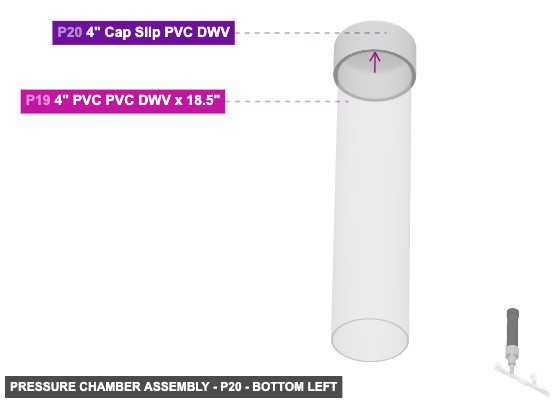
Angle: bottom left
P5 (1" Tube 3" length) - attach its 1" M SLIP #1 facing top to part 6's 1" F SLIP #1, also connect its 1" M SLIP #2 oriented bottom links with part 4's 1" F SLIP #3
P6 (1" x 2" Reducer Slip PVC) - attach its 1" F SLIP #1 facing bottom to part 5's 1" M SLIP #1. Also, connect its 2" F SLIP #1 oriented top links with part 7's 2" M SLIP #2
P7 (2" Tube 3" length) - its 2" M SLIP #1, which is top-facing, should connect to part 8's 2" F SLIP #1, also attach its 2" M SLIP #2 facing bottom to part 6's 2" F SLIP #1
P8 (2" x 4" Reducer Slip PVC) - connect its 2" F SLIP #1 oriented bottom links with part 7's 2" M SLIP #1, plus connect its 4" M SLIP #1 oriented top links with part 18's 4" DWV F #1
P18 (4¨ Coupler H x H PVC DWV) - attach its 4" DWV F #1 facing bottom to part 8's 4" M SLIP #1. Also, its 4" DWV F #2, which is top-facing, should connect to part 19's 4" M SLIP #2
P19 (4" PVC PVC DWV 18.5" length) - connect its 4" M SLIP #1 oriented top links with part 20's 4" F SLIP #1, and its 4" M SLIP #2, which is bottom-facing, should connect to part 18's 4" DWV F #2
P20 (4" Cap Slip PVC DWV) - its 4" F SLIP #1, which is bottom-facing, should connect to part 19's 4" M SLIP #1
1" Tube x 3"x 1 1" x 2" Reducer Slip PVCx 1 2" Tube x 3"x 1 2" x 4" Reducer Slip PVCx 1 4¨ Coupler H x H PVC DWVx 1 4" PVC PVC DWV x 18.5"x 1 4" Cap Slip PVC DWVx 1
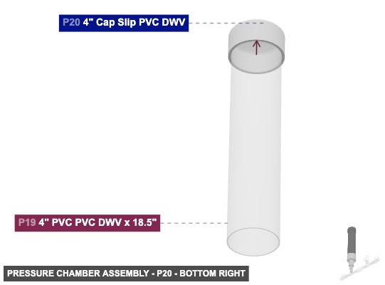
Angle: bottom right
P5 (1" Tube 3" length) - attach its 1" M SLIP #1 facing top to part 6's 1" F SLIP #1, also connect its 1" M SLIP #2 oriented bottom links with part 4's 1" F SLIP #3
P6 (1" x 2" Reducer Slip PVC) - attach its 1" F SLIP #1 facing bottom to part 5's 1" M SLIP #1. Also, connect its 2" F SLIP #1 oriented top links with part 7's 2" M SLIP #2
P7 (2" Tube 3" length) - its 2" M SLIP #1, which is top-facing, should connect to part 8's 2" F SLIP #1, also attach its 2" M SLIP #2 facing bottom to part 6's 2" F SLIP #1
P8 (2" x 4" Reducer Slip PVC) - connect its 2" F SLIP #1 oriented bottom links with part 7's 2" M SLIP #1, plus connect its 4" M SLIP #1 oriented top links with part 18's 4" DWV F #1
P18 (4¨ Coupler H x H PVC DWV) - attach its 4" DWV F #1 facing bottom to part 8's 4" M SLIP #1. Also, its 4" DWV F #2, which is top-facing, should connect to part 19's 4" M SLIP #2
P19 (4" PVC PVC DWV 18.5" length) - connect its 4" M SLIP #1 oriented top links with part 20's 4" F SLIP #1, and its 4" M SLIP #2, which is bottom-facing, should connect to part 18's 4" DWV F #2
P20 (4" Cap Slip PVC DWV) - its 4" F SLIP #1, which is bottom-facing, should connect to part 19's 4" M SLIP #1
1" Tube x 3"x 1 1" x 2" Reducer Slip PVCx 1 2" Tube x 3"x 1 2" x 4" Reducer Slip PVCx 1 4¨ Coupler H x H PVC DWVx 1 4" PVC PVC DWV x 18.5"x 1 4" Cap Slip PVC DWVx 1 Attaching: Waste Valve Line and Secondary Tee
Forms the path for the waste valve (P10) and connects to the delivery line tee (P12).
Connect the left 1" Male SLIP of P9 to the right 1" Female SLIP of P4 in Group 1. The Delivery Valve & Outlet (Group 4) connects to the top 1" Female Threaded and right 1" Female SLIP of P12.
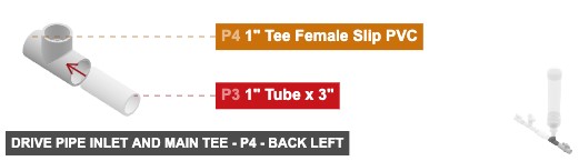
Angle: back left
P9 (1" Tube 3" length) - its 1" M SLIP #1, which is right-facing, should connect to part 10's 1" F SLIP #1. Additionally, its 1" M SLIP #2, which is left-facing, should connect to part 4's 1" F SLIP #2
P10 (1" Check Valve Slip PVC) - attach its 1" F SLIP #1 facing left to part 9's 1" M SLIP #1. Additionally, connect its 1" F SLIP #2 oriented right links with part 11's 1" M SLIP #2
P11 (1" Tube 3" length) - its 1" M SLIP #1, which is right-facing, should connect to part 12's 1" F SLIP #1, and connect its 1" M SLIP #2 oriented left links with part 10's 1" F SLIP #2
P12 (1" Tee F Threaded PVC) - attach its 1" F SLIP #1 facing left to part 11's 1" M SLIP #1. After that, connect its 1" F SLIP #2 oriented right links with part 14's 1" M SLIP #2. Next, attach its 1" F Threaded #1 facing top to part 13's 1" M Threaded #1
1" Tube x 3"x 2 1" Check Valve Slip PVCx 1 1" Tee Female Threaded PVCx 1
Angle: back right
P9 (1" Tube 3" length) - its 1" M SLIP #1, which is right-facing, should connect to part 10's 1" F SLIP #1. Additionally, its 1" M SLIP #2, which is left-facing, should connect to part 4's 1" F SLIP #2
P10 (1" Check Valve Slip PVC) - attach its 1" F SLIP #1 facing left to part 9's 1" M SLIP #1. Additionally, connect its 1" F SLIP #2 oriented right links with part 11's 1" M SLIP #2
P11 (1" Tube 3" length) - its 1" M SLIP #1, which is right-facing, should connect to part 12's 1" F SLIP #1, and connect its 1" M SLIP #2 oriented left links with part 10's 1" F SLIP #2
P12 (1" Tee F Threaded PVC) - attach its 1" F SLIP #1 facing left to part 11's 1" M SLIP #1. After that, connect its 1" F SLIP #2 oriented right links with part 14's 1" M SLIP #2. Next, attach its 1" F Threaded #1 facing top to part 13's 1" M Threaded #1
1" Tube x 3"x 2 1" Check Valve Slip PVCx 1 1" Tee Female Threaded PVCx 1
Angle: front left
P9 (1" Tube 3" length) - its 1" M SLIP #1, which is right-facing, should connect to part 10's 1" F SLIP #1. Additionally, its 1" M SLIP #2, which is left-facing, should connect to part 4's 1" F SLIP #2
P10 (1" Check Valve Slip PVC) - attach its 1" F SLIP #1 facing left to part 9's 1" M SLIP #1. Additionally, connect its 1" F SLIP #2 oriented right links with part 11's 1" M SLIP #2
P11 (1" Tube 3" length) - its 1" M SLIP #1, which is right-facing, should connect to part 12's 1" F SLIP #1, and connect its 1" M SLIP #2 oriented left links with part 10's 1" F SLIP #2
P12 (1" Tee F Threaded PVC) - attach its 1" F SLIP #1 facing left to part 11's 1" M SLIP #1. After that, connect its 1" F SLIP #2 oriented right links with part 14's 1" M SLIP #2. Next, attach its 1" F Threaded #1 facing top to part 13's 1" M Threaded #1
1" Tube x 3"x 2 1" Check Valve Slip PVCx 1 1" Tee Female Threaded PVCx 1
Angle: front right
P9 (1" Tube 3" length) - its 1" M SLIP #1, which is right-facing, should connect to part 10's 1" F SLIP #1. Additionally, its 1" M SLIP #2, which is left-facing, should connect to part 4's 1" F SLIP #2
P10 (1" Check Valve Slip PVC) - attach its 1" F SLIP #1 facing left to part 9's 1" M SLIP #1. Additionally, connect its 1" F SLIP #2 oriented right links with part 11's 1" M SLIP #2
P11 (1" Tube 3" length) - its 1" M SLIP #1, which is right-facing, should connect to part 12's 1" F SLIP #1, and connect its 1" M SLIP #2 oriented left links with part 10's 1" F SLIP #2
P12 (1" Tee F Threaded PVC) - attach its 1" F SLIP #1 facing left to part 11's 1" M SLIP #1. After that, connect its 1" F SLIP #2 oriented right links with part 14's 1" M SLIP #2. Next, attach its 1" F Threaded #1 facing top to part 13's 1" M Threaded #1
1" Tube x 3"x 2 1" Check Valve Slip PVCx 1 1" Tee Female Threaded PVCx 1
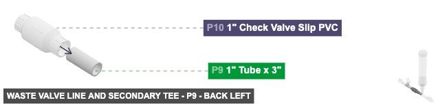
Angle: bottom left
P9 (1" Tube 3" length) - its 1" M SLIP #1, which is right-facing, should connect to part 10's 1" F SLIP #1. Additionally, its 1" M SLIP #2, which is left-facing, should connect to part 4's 1" F SLIP #2
P10 (1" Check Valve Slip PVC) - attach its 1" F SLIP #1 facing left to part 9's 1" M SLIP #1. Additionally, connect its 1" F SLIP #2 oriented right links with part 11's 1" M SLIP #2
P11 (1" Tube 3" length) - its 1" M SLIP #1, which is right-facing, should connect to part 12's 1" F SLIP #1, and connect its 1" M SLIP #2 oriented left links with part 10's 1" F SLIP #2
P12 (1" Tee F Threaded PVC) - attach its 1" F SLIP #1 facing left to part 11's 1" M SLIP #1. After that, connect its 1" F SLIP #2 oriented right links with part 14's 1" M SLIP #2. Next, attach its 1" F Threaded #1 facing top to part 13's 1" M Threaded #1
1" Tube x 3"x 2 1" Check Valve Slip PVCx 1 1" Tee Female Threaded PVCx 1
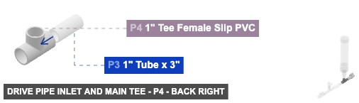
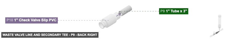
Angle: bottom right
P9 (1" Tube 3" length) - its 1" M SLIP #1, which is right-facing, should connect to part 10's 1" F SLIP #1. Additionally, its 1" M SLIP #2, which is left-facing, should connect to part 4's 1" F SLIP #2
P10 (1" Check Valve Slip PVC) - attach its 1" F SLIP #1 facing left to part 9's 1" M SLIP #1. Additionally, connect its 1" F SLIP #2 oriented right links with part 11's 1" M SLIP #2
P11 (1" Tube 3" length) - its 1" M SLIP #1, which is right-facing, should connect to part 12's 1" F SLIP #1, and connect its 1" M SLIP #2 oriented left links with part 10's 1" F SLIP #2
P12 (1" Tee F Threaded PVC) - attach its 1" F SLIP #1 facing left to part 11's 1" M SLIP #1. After that, connect its 1" F SLIP #2 oriented right links with part 14's 1" M SLIP #2. Next, attach its 1" F Threaded #1 facing top to part 13's 1" M Threaded #1
1" Tube x 3"x 2 1" Check Valve Slip PVCx 1 1" Tee Female Threaded PVCx 1 Attaching: Delivery Valve and Outlet
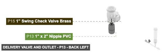
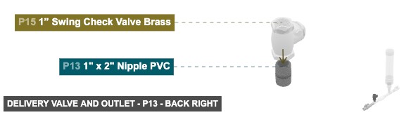
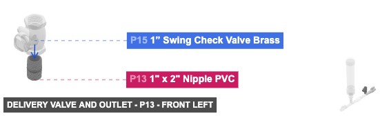
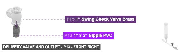
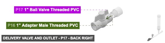
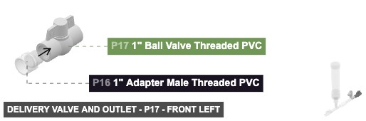
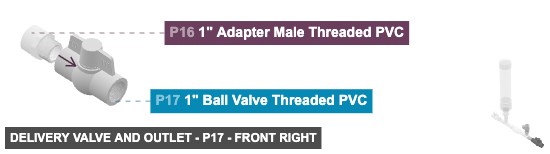
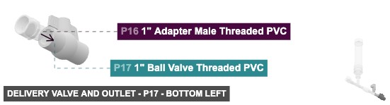
Forms the final delivery path for the pumped water, including the delivery check valve (P15) and outlet valve (P17).
Connect the bottom 1" Male Threaded of P13 to the top 1" Female Threaded of P12 in Group 3. Connect the left 1" Male SLIP of P14 to the right 1" Female SLIP of P12 in Group 3.
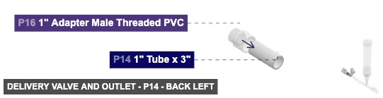
Angle: back left
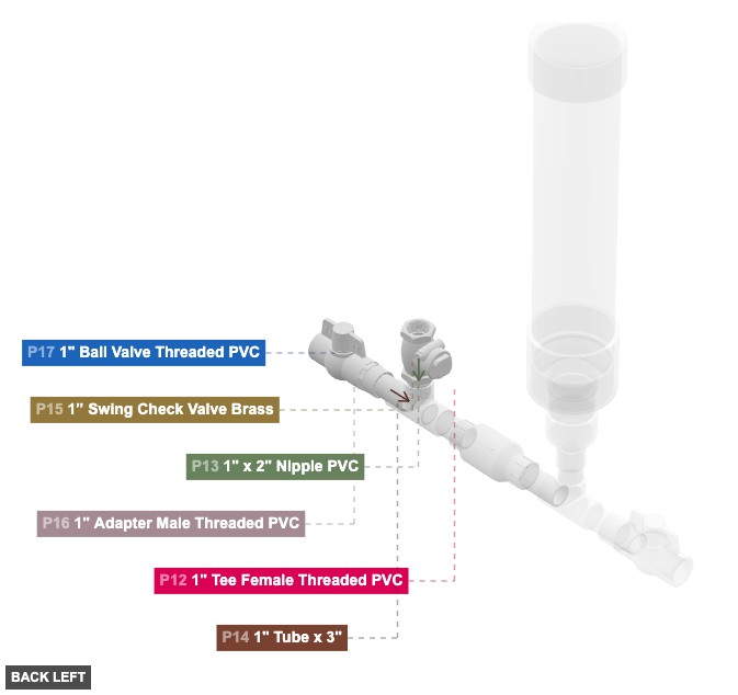
P13 (1" x 2" Nipple PVC) - connect its 1" M Threaded #1 oriented bottom links with part 12's 1" F Threaded #1, plus its 1" M Threaded #2, which is top-facing, should connect to part 15's 1" F Threaded #2
P14 (1" Tube 3" length) - attach its 1" M SLIP #1 facing right to part 16's 1" F SLIP #1, then its 1" M SLIP #2, which is left-facing, should connect to part 12's 1" F SLIP #2
P15 (1” Swing Check Valve Brass) - its 1" F Threaded #2, which is bottom-facing, should connect to part 13's 1" M Threaded #2. Also, its 1" F Threaded #1 should be directed top
P16 (1" Adapter M Threaded PVC) - connect its 1" M Threaded #1 oriented right links with part 17's 1" F Threaded #1. After that, attach its 1" F SLIP #1 facing left to part 14's 1" M SLIP #1
P17 (1" Ball Valve Threaded PVC) - attach its 1" F Threaded #1 facing left to part 16's 1" M Threaded #1. Also, its 1" F Threaded #2 needs to point right
1" x 2" Nipple PVCx 1 1" Tube x 3"x 1 1” Swing Check Valve Brassx 1 1" Adapter Male Threaded PVCx 1 1" Ball Valve Threaded PVCx 1
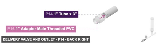
Angle: back right
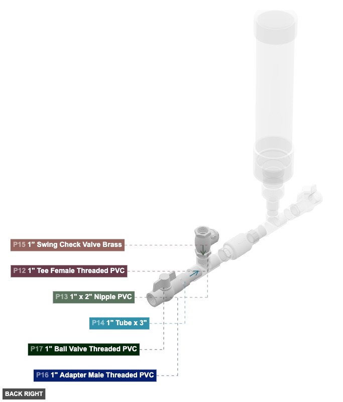
P13 (1" x 2" Nipple PVC) - connect its 1" M Threaded #1 oriented bottom links with part 12's 1" F Threaded #1, plus its 1" M Threaded #2, which is top-facing, should connect to part 15's 1" F Threaded #2
P14 (1" Tube 3" length) - attach its 1" M SLIP #1 facing right to part 16's 1" F SLIP #1, then its 1" M SLIP #2, which is left-facing, should connect to part 12's 1" F SLIP #2
P15 (1” Swing Check Valve Brass) - its 1" F Threaded #2, which is bottom-facing, should connect to part 13's 1" M Threaded #2. Also, its 1" F Threaded #1 should be directed top
P16 (1" Adapter M Threaded PVC) - connect its 1" M Threaded #1 oriented right links with part 17's 1" F Threaded #1. After that, attach its 1" F SLIP #1 facing left to part 14's 1" M SLIP #1
P17 (1" Ball Valve Threaded PVC) - attach its 1" F Threaded #1 facing left to part 16's 1" M Threaded #1. Also, its 1" F Threaded #2 needs to point right
1" x 2" Nipple PVCx 1 1" Tube x 3"x 1 1” Swing Check Valve Brassx 1 1" Adapter Male Threaded PVCx 1 1" Ball Valve Threaded PVCx 1
Angle: front left
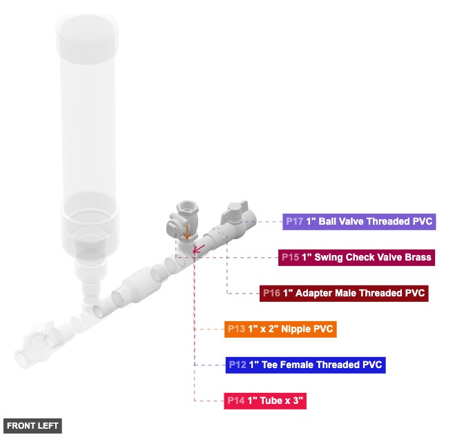
P13 (1" x 2" Nipple PVC) - connect its 1" M Threaded #1 oriented bottom links with part 12's 1" F Threaded #1, plus its 1" M Threaded #2, which is top-facing, should connect to part 15's 1" F Threaded #2
P14 (1" Tube 3" length) - attach its 1" M SLIP #1 facing right to part 16's 1" F SLIP #1, then its 1" M SLIP #2, which is left-facing, should connect to part 12's 1" F SLIP #2
P15 (1” Swing Check Valve Brass) - its 1" F Threaded #2, which is bottom-facing, should connect to part 13's 1" M Threaded #2. Also, its 1" F Threaded #1 should be directed top
P16 (1" Adapter M Threaded PVC) - connect its 1" M Threaded #1 oriented right links with part 17's 1" F Threaded #1. After that, attach its 1" F SLIP #1 facing left to part 14's 1" M SLIP #1
P17 (1" Ball Valve Threaded PVC) - attach its 1" F Threaded #1 facing left to part 16's 1" M Threaded #1. Also, its 1" F Threaded #2 needs to point right
1" x 2" Nipple PVCx 1 1" Tube x 3"x 1 1” Swing Check Valve Brassx 1 1" Adapter Male Threaded PVCx 1 1" Ball Valve Threaded PVCx 1
Angle: front right

P13 (1" x 2" Nipple PVC) - connect its 1" M Threaded #1 oriented bottom links with part 12's 1" F Threaded #1, plus its 1" M Threaded #2, which is top-facing, should connect to part 15's 1" F Threaded #2
P14 (1" Tube 3" length) - attach its 1" M SLIP #1 facing right to part 16's 1" F SLIP #1, then its 1" M SLIP #2, which is left-facing, should connect to part 12's 1" F SLIP #2
P15 (1” Swing Check Valve Brass) - its 1" F Threaded #2, which is bottom-facing, should connect to part 13's 1" M Threaded #2. Also, its 1" F Threaded #1 should be directed top
P16 (1" Adapter M Threaded PVC) - connect its 1" M Threaded #1 oriented right links with part 17's 1" F Threaded #1. After that, attach its 1" F SLIP #1 facing left to part 14's 1" M SLIP #1
P17 (1" Ball Valve Threaded PVC) - attach its 1" F Threaded #1 facing left to part 16's 1" M Threaded #1. Also, its 1" F Threaded #2 needs to point right
1" x 2" Nipple PVCx 1 1" Tube x 3"x 1 1” Swing Check Valve Brassx 1 1" Adapter Male Threaded PVCx 1 1" Ball Valve Threaded PVCx 1
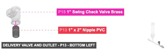
Angle: bottom left
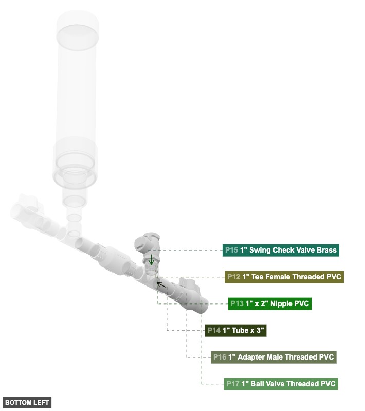
P13 (1" x 2" Nipple PVC) - connect its 1" M Threaded #1 oriented bottom links with part 12's 1" F Threaded #1, plus its 1" M Threaded #2, which is top-facing, should connect to part 15's 1" F Threaded #2
P14 (1" Tube 3" length) - attach its 1" M SLIP #1 facing right to part 16's 1" F SLIP #1, then its 1" M SLIP #2, which is left-facing, should connect to part 12's 1" F SLIP #2
P15 (1” Swing Check Valve Brass) - its 1" F Threaded #2, which is bottom-facing, should connect to part 13's 1" M Threaded #2. Also, its 1" F Threaded #1 should be directed top
P16 (1" Adapter M Threaded PVC) - connect its 1" M Threaded #1 oriented right links with part 17's 1" F Threaded #1. After that, attach its 1" F SLIP #1 facing left to part 14's 1" M SLIP #1
P17 (1" Ball Valve Threaded PVC) - attach its 1" F Threaded #1 facing left to part 16's 1" M Threaded #1. Also, its 1" F Threaded #2 needs to point right
1" x 2" Nipple PVCx 1 1" Tube x 3"x 1 1” Swing Check Valve Brassx 1 1" Adapter Male Threaded PVCx 1 1" Ball Valve Threaded PVCx 1
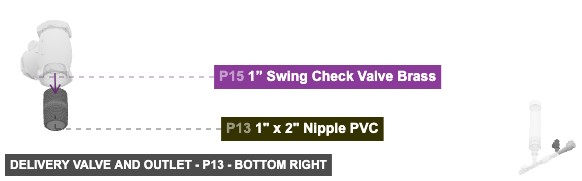
Angle: bottom right
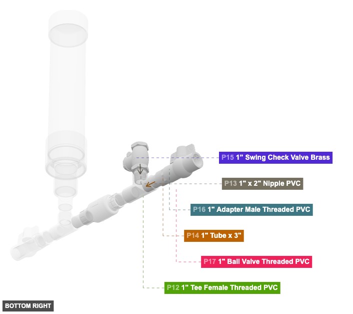
P13 (1" x 2" Nipple PVC) - connect its 1" M Threaded #1 oriented bottom links with part 12's 1" F Threaded #1, plus its 1" M Threaded #2, which is top-facing, should connect to part 15's 1" F Threaded #2
P14 (1" Tube 3" length) - attach its 1" M SLIP #1 facing right to part 16's 1" F SLIP #1, then its 1" M SLIP #2, which is left-facing, should connect to part 12's 1" F SLIP #2
P15 (1” Swing Check Valve Brass) - its 1" F Threaded #2, which is bottom-facing, should connect to part 13's 1" M Threaded #2. Also, its 1" F Threaded #1 should be directed top
P16 (1" Adapter M Threaded PVC) - connect its 1" M Threaded #1 oriented right links with part 17's 1" F Threaded #1. After that, attach its 1" F SLIP #1 facing left to part 14's 1" M SLIP #1
P17 (1" Ball Valve Threaded PVC) - attach its 1" F Threaded #1 facing left to part 16's 1" M Threaded #1. Also, its 1" F Threaded #2 needs to point right
1" x 2" Nipple PVCx 1 1" Tube x 3"x 1 1” Swing Check Valve Brassx 1 1" Adapter Male Threaded PVCx 1 1" Ball Valve Threaded PVCx 1