A four-wheeled support structure for a dog, likely for hind leg mobility assistance. It features two large primary wheels, a PVC pipe frame with various connectors (Tees, Elbows, Wyes, 4-Ways), and adjustable rear supports. - Medium Sized Dog Wheelchair
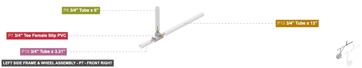
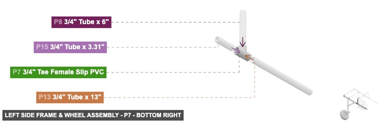
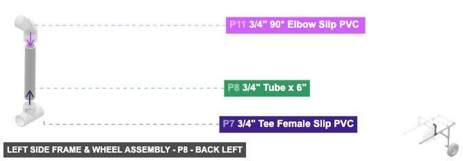
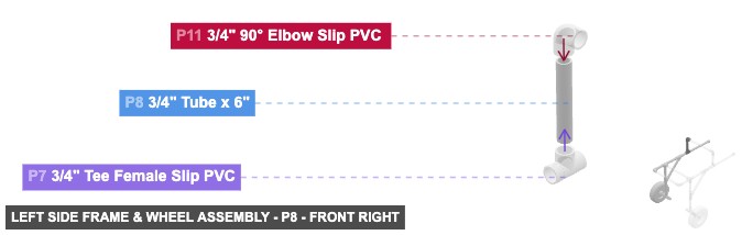
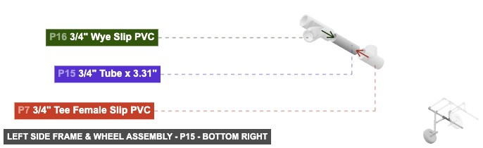
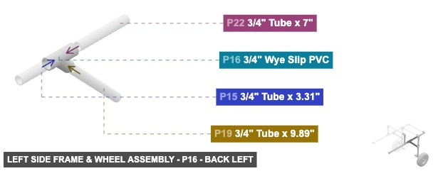
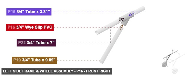
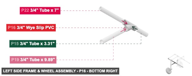
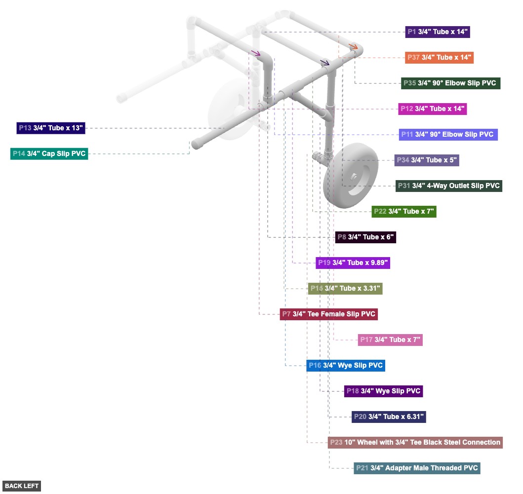
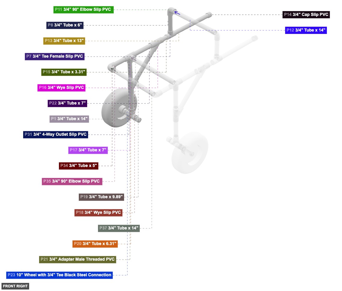
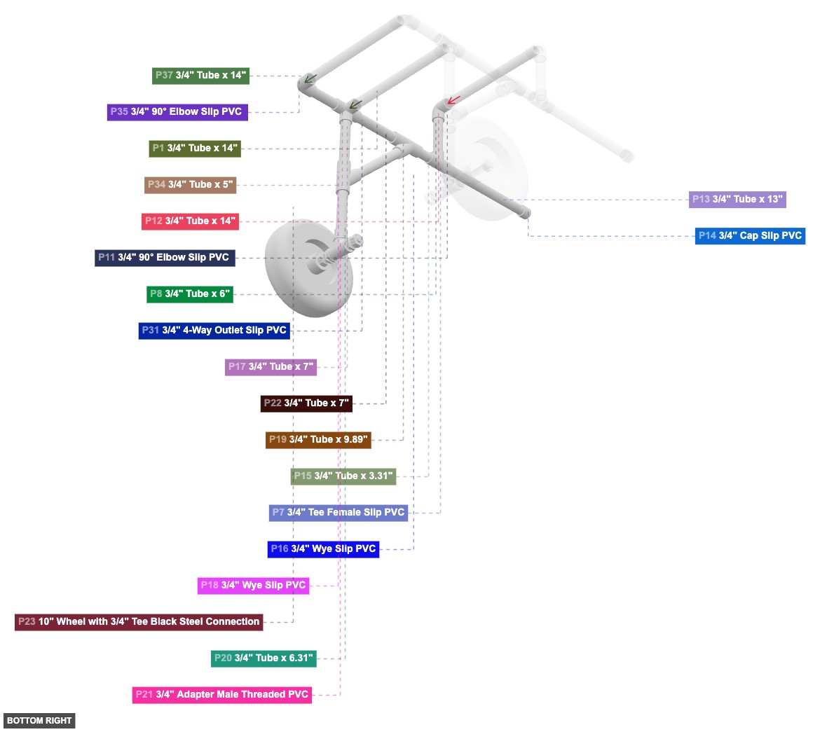
Forms the complete left side structure including the wheel, lower frame, upper supports, and connection points.
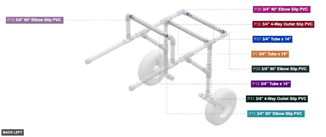
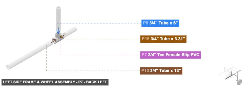
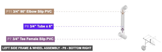
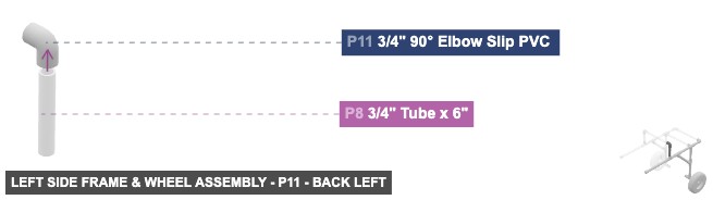
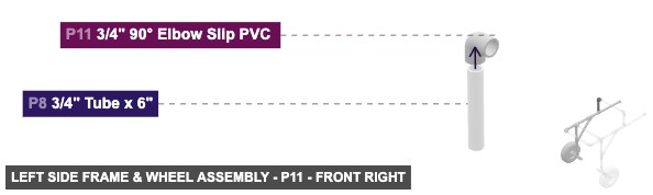
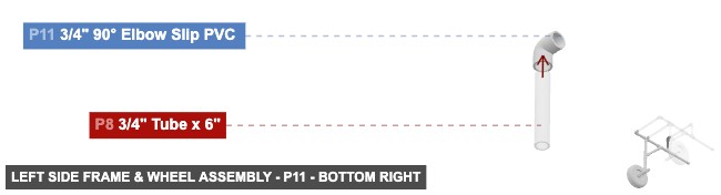
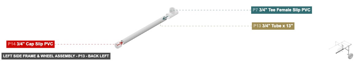
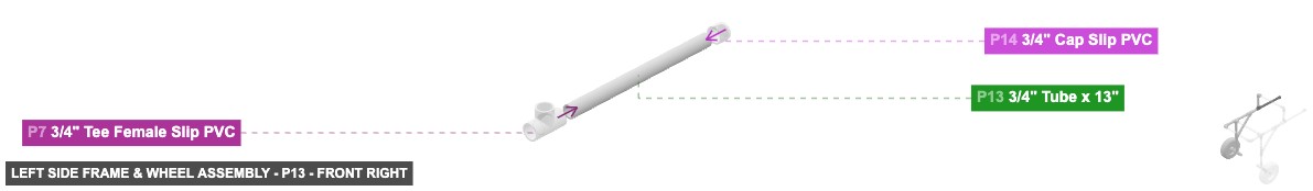
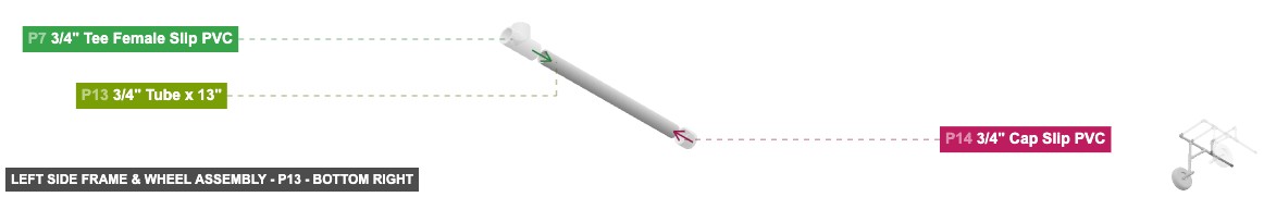
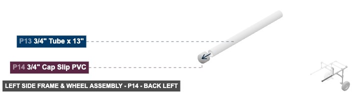
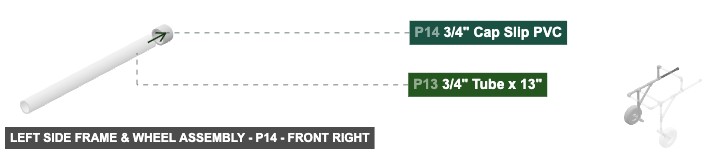
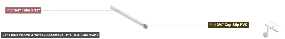
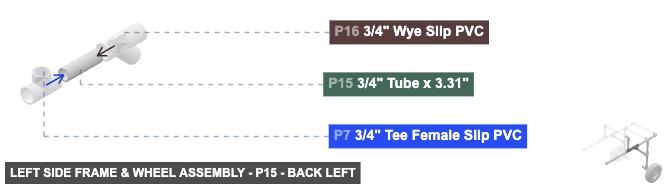
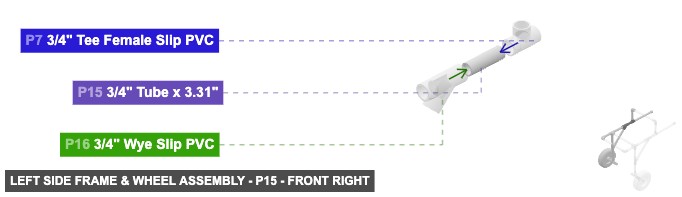
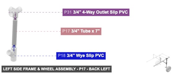
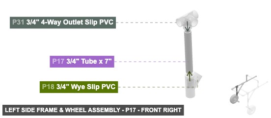
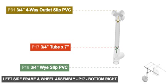
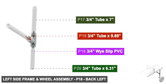
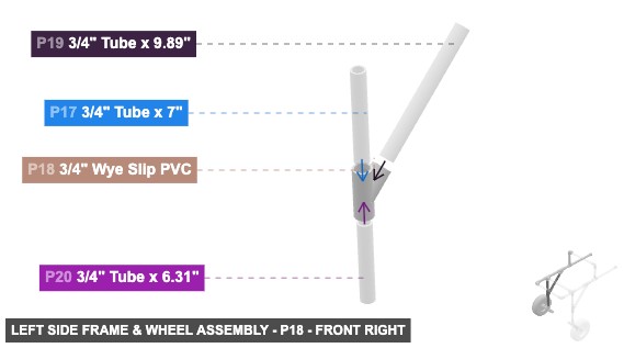
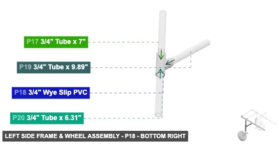
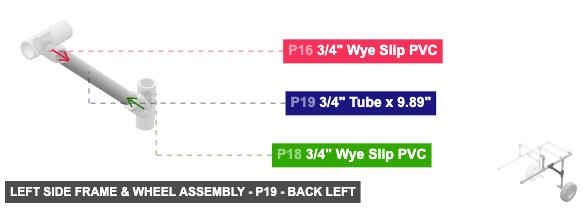
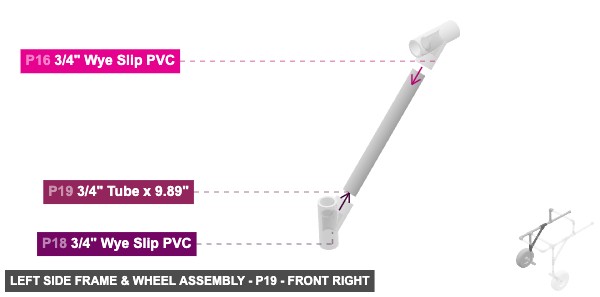
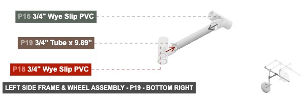
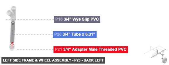
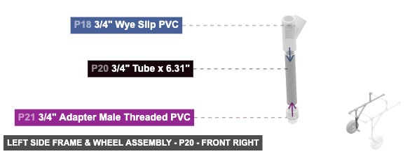
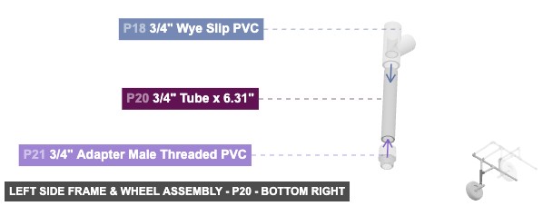
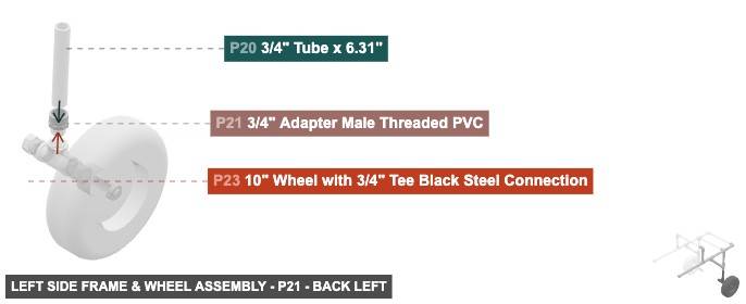
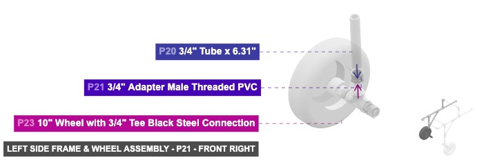
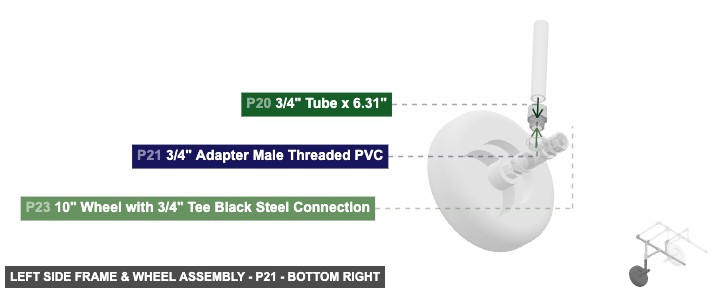
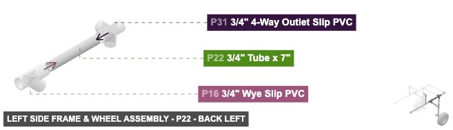
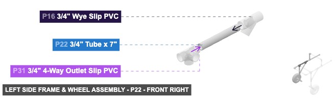
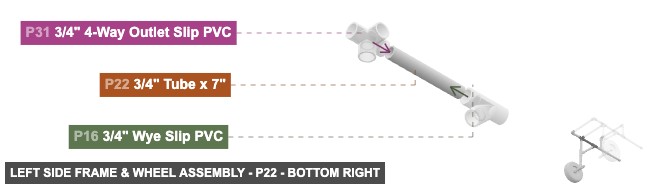
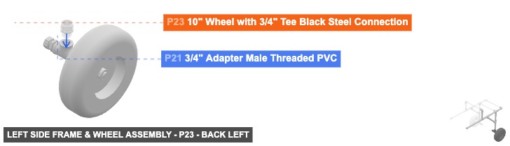
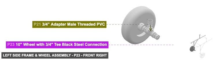
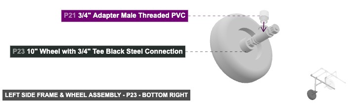
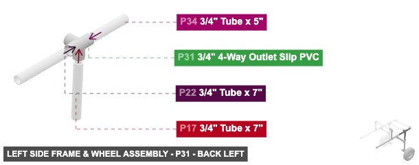
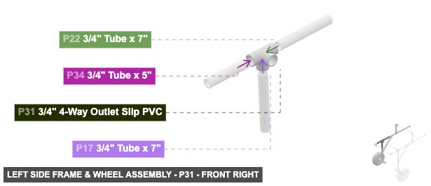
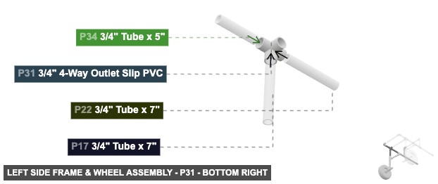
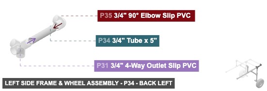
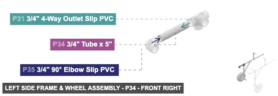
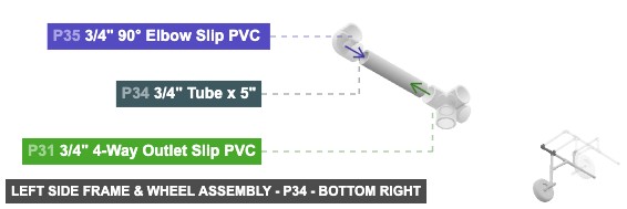
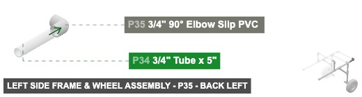
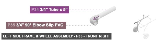
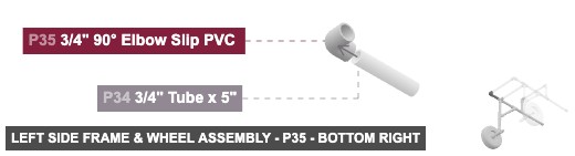
1. Assemble wheel unit: Connect P23 (Wheel) to P21 (Adapter M Threaded PVC) via their 3/4" Threaded connections. Connect the Male SLIP 3/4" end of P20 (Tube 6.31") to the Female SLIP 3/4" connection on P21. 2. Assemble lower Wye: Connect the other Male SLIP 3/4" end of P20 to the bottom Female SLIP 3/4" connection on P18 (Wye Slip PVC). Connect the Male SLIP 3/4" end of P17 (Tube 7") to the top Female SLIP 3/4" connection on P18. Connect one Male SLIP 3/4" end of P19 (Tube 9.89") to the angled back-top Female SLIP 3/4" connection on P18. 3. Assemble upper Wye: Connect the other Male SLIP 3/4" end of P19 to the angled front-bottom Female SLIP 3/4" connection on P16 (Wye Slip PVC). Connect the Male SLIP 3/4" end of P15 (Tube 3.31") to the back Female SLIP 3/4" connection on P16. Connect the Male SLIP 3/4" end of P22 (Tube 7") to the front Female SLIP 3/4" connection on P16. 4. Assemble rear support: Connect the other Male SLIP 3/4" end of P15 to the front Female SLIP 3/4" connection on P7 (Tee F Slip PVC). Connect the Male SLIP 3/4" end of P13 (Tube 13") to the back Female SLIP 3/4" connection on P7. Attach P14 (Cap Slip PVC) to the other Male SLIP 3/4" end of P13. Connect the Male SLIP 3/4" end of P8 (Tube 6") to the top Female SLIP 3/4" connection on P7. Connect the other Male SLIP 3/4" end of P8 to a Female SLIP 3/4" connection on P11 (90° Elbow Slip PVC). 5. Assemble main connector: Connect the other Male SLIP 3/4" end of P17 to the bottom Female SLIP 3/4" connection on P31 (4-Way Outlet Slip PVC). Connect the other Male SLIP 3/4" end of P22 to the back Female SLIP 3/4" connection on P31. Connect the Male SLIP 3/4" end of P34 (Tube 5") to the front Female SLIP 3/4" connection on P31. Connect the other Male SLIP 3/4" end of P34 to a Female SLIP 3/4" connection on P35 (90° Elbow Slip PVC).
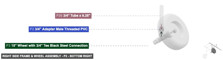
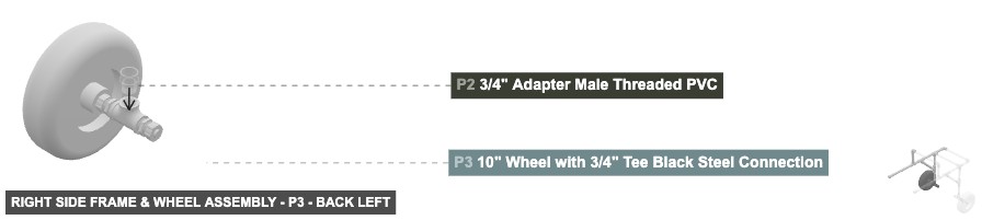
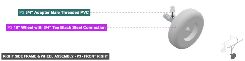
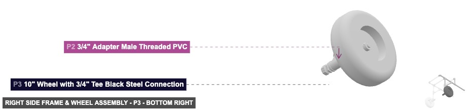
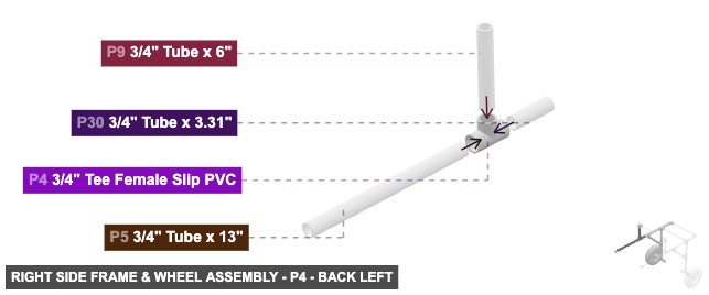
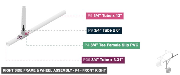
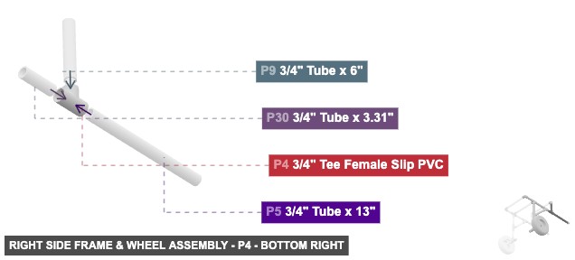
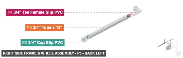
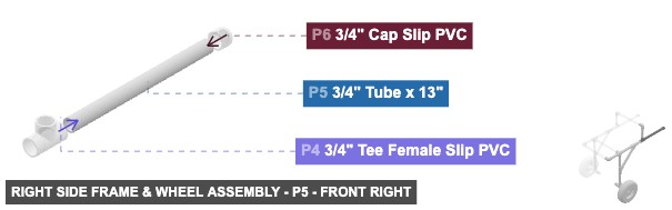
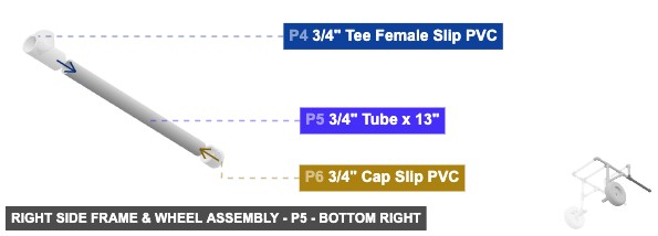
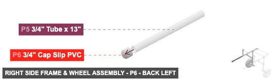
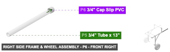
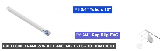
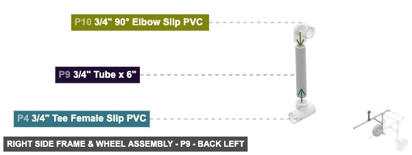
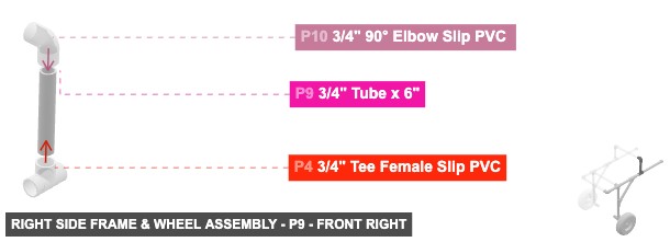
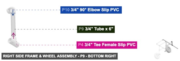
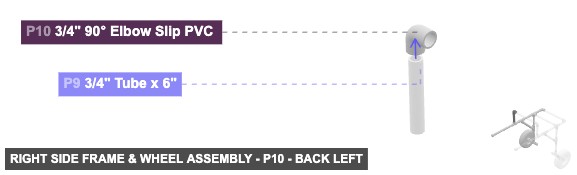
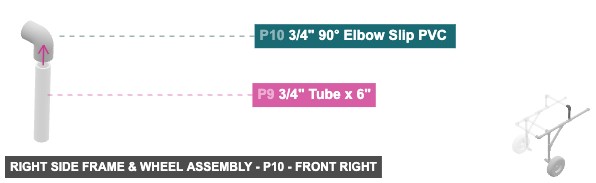
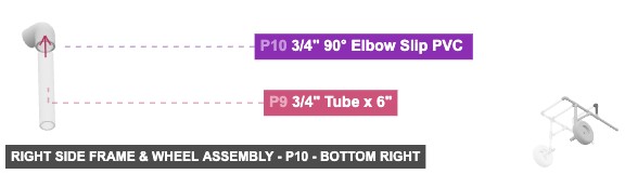
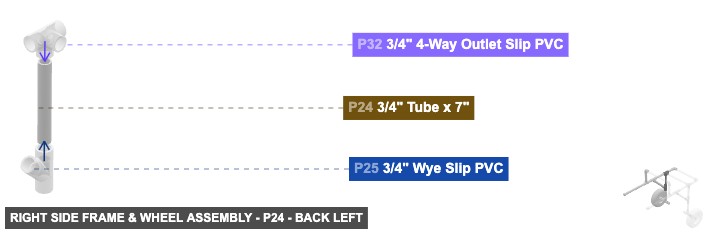
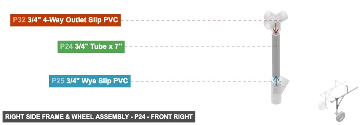
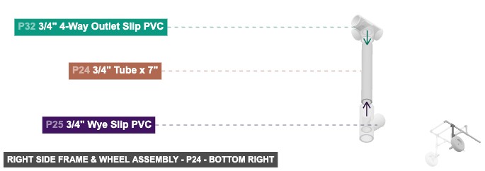
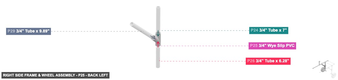
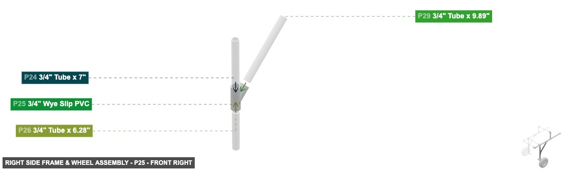
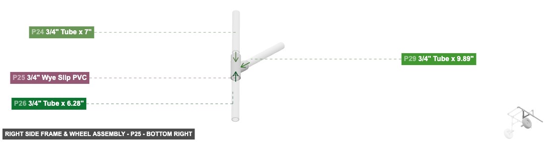
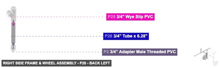
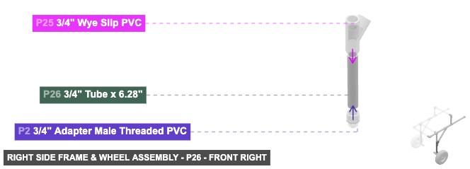
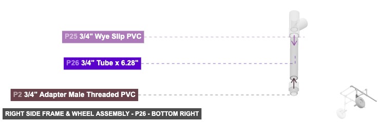
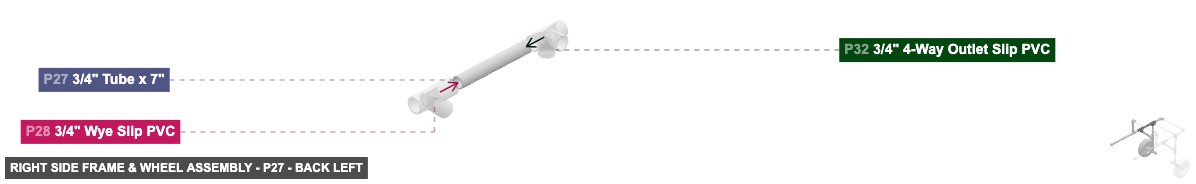
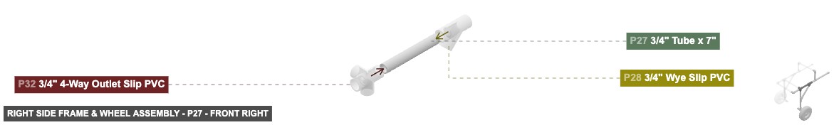
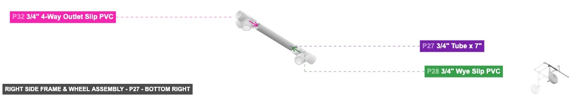
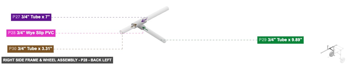
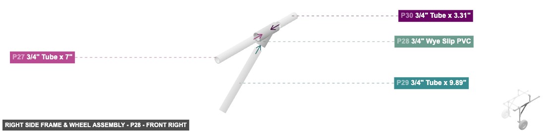
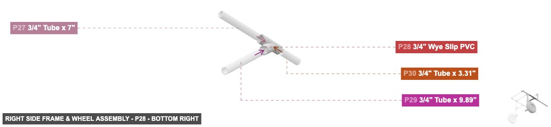
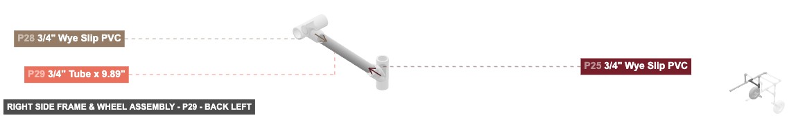
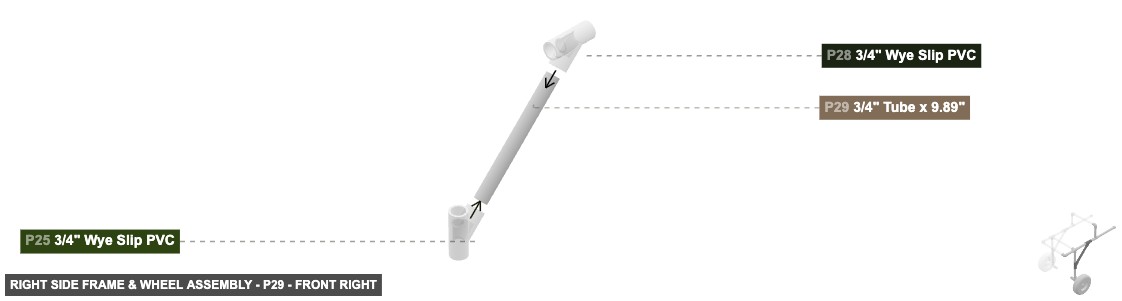
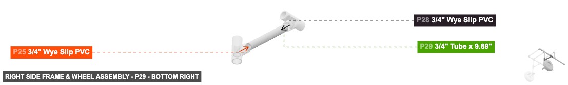
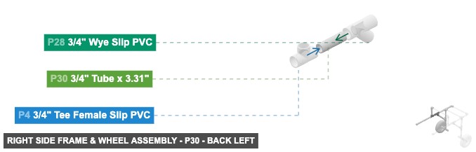
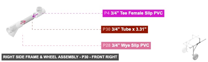
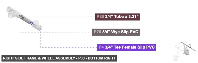
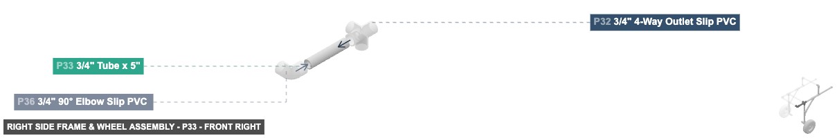
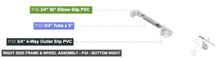
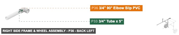
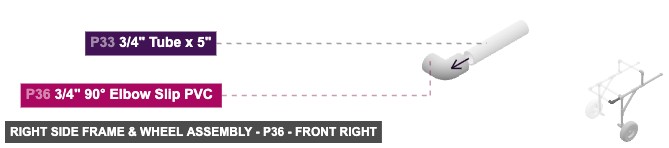
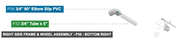
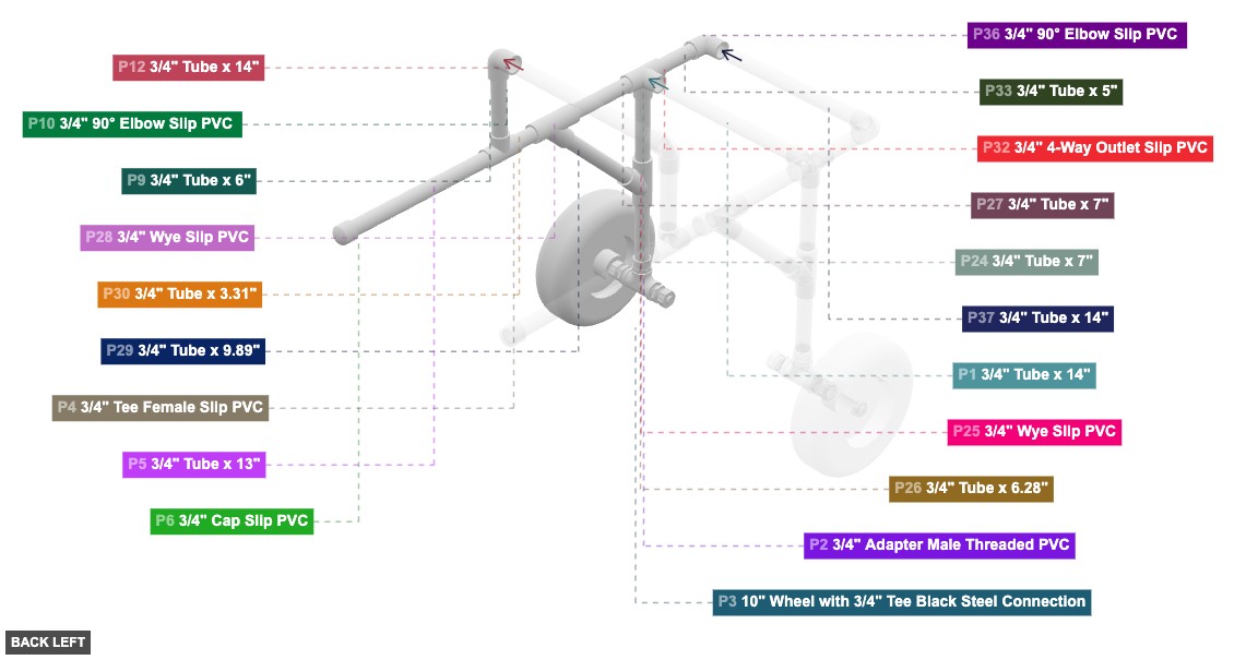
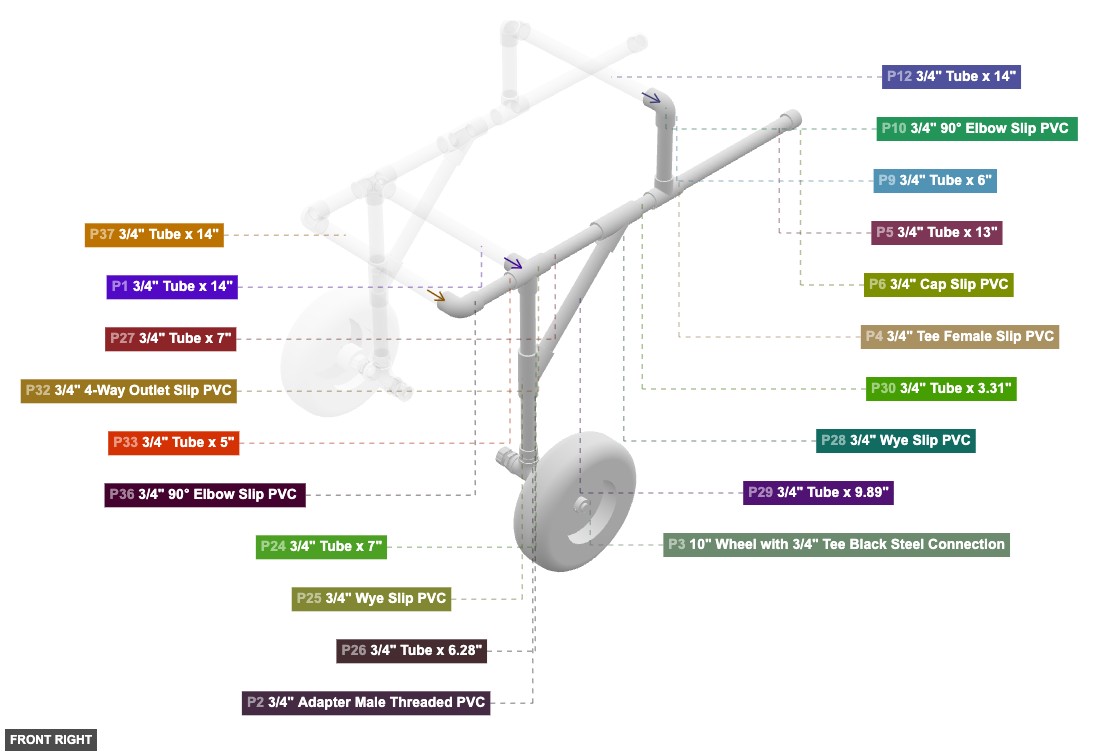
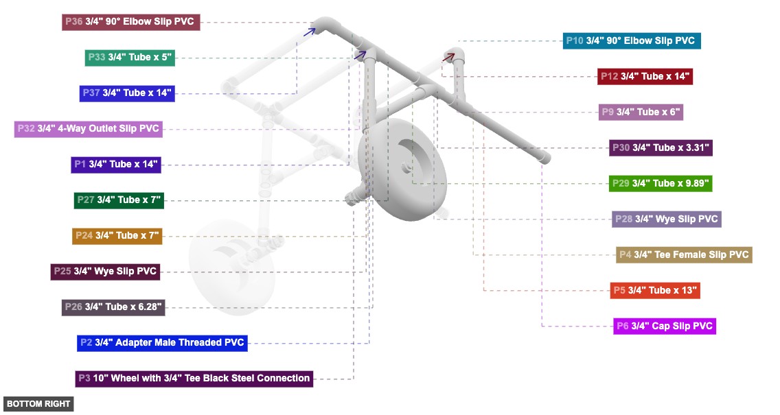
Forms the complete right side structure including the wheel, lower frame, upper supports, and connection points.
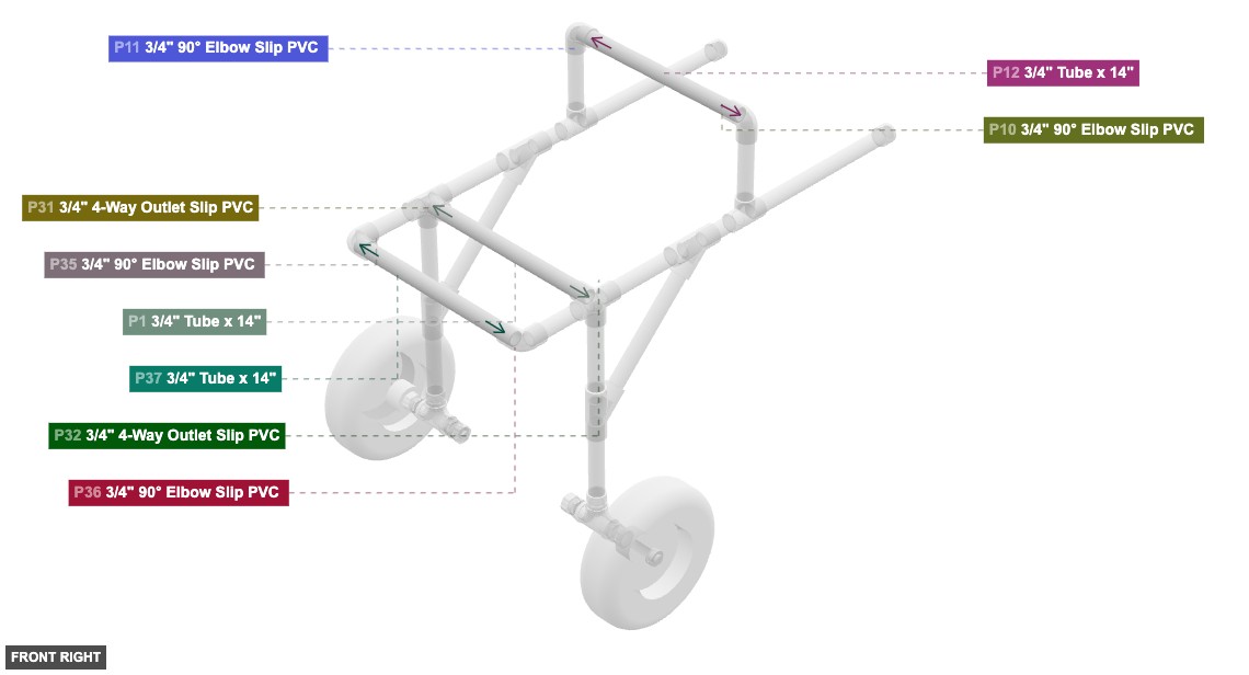
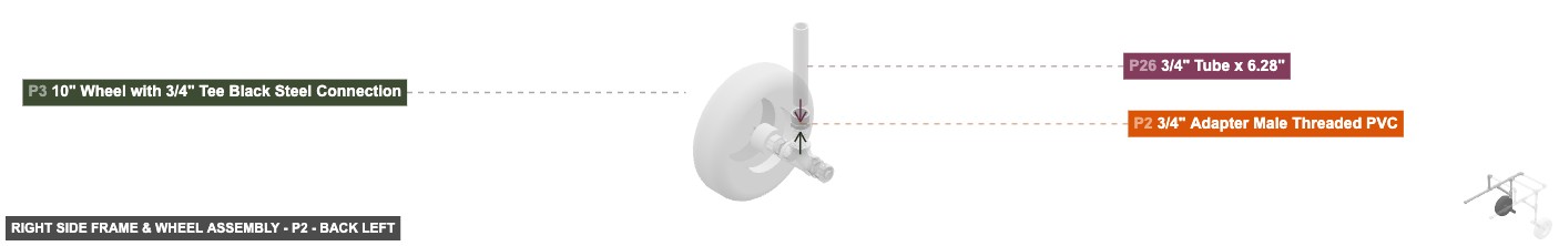
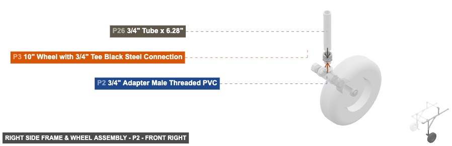
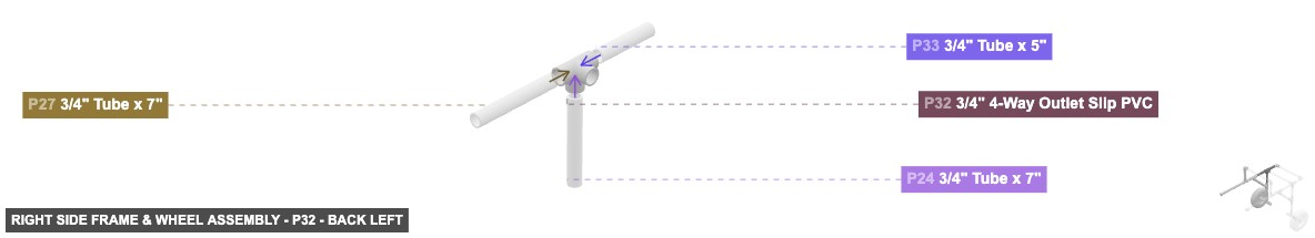
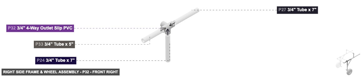
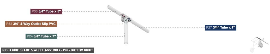
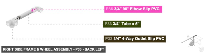
1. Assemble wheel unit: Connect P3 (Wheel) to P2 (Adapter M Threaded PVC) via their 3/4" Threaded connections. Connect the Male SLIP 3/4" end of P26 (Tube 6.28") to the Female SLIP 3/4" connection on P2. 2. Assemble lower Wye: Connect the other Male SLIP 3/4" end of P26 to the bottom Female SLIP 3/4" connection on P25 (Wye Slip PVC). Connect the Male SLIP 3/4" end of P24 (Tube 7") to the top Female SLIP 3/4" connection on P25. Connect one Male SLIP 3/4" end of P29 (Tube 9.89") to the angled back-top Female SLIP 3/4" connection on P25. 3. Assemble upper Wye: Connect the other Male SLIP 3/4" end of P29 to the angled front-bottom Female SLIP 3/4" connection on P28 (Wye Slip PVC). Connect the Male SLIP 3/4" end of P30 (Tube 3.31") to the back Female SLIP 3/4" connection on P28. Connect the Male SLIP 3/4" end of P27 (Tube 7") to the front Female SLIP 3/4" connection on P28. 4. Assemble rear support: Connect the other Male SLIP 3/4" end of P30 to the front Female SLIP 3/4" connection on P4 (Tee F Slip PVC). Connect the Male SLIP 3/4" end of P5 (Tube 13") to the back Female SLIP 3/4" connection on P4. Attach P6 (Cap Slip PVC) to the other Male SLIP 3/4" end of P5. Connect the Male SLIP 3/4" end of P9 (Tube 6") to the top Female SLIP 3/4" connection on P4. Connect the other Male SLIP 3/4" end of P9 to a Female SLIP 3/4" connection on P10 (90° Elbow Slip PVC). 5. Assemble main connector: Connect the other Male SLIP 3/4" end of P24 to the bottom Female SLIP 3/4" connection on P32 (4-Way Outlet Slip PVC). Connect the other Male SLIP 3/4" end of P27 to the back Female SLIP 3/4" connection on P32. Connect the Male SLIP 3/4" end of P33 (Tube 5") to the front Female SLIP 3/4" connection on P32. Connect the other Male SLIP 3/4" end of P33 to a Female SLIP 3/4" connection on P36 (90° Elbow Slip PVC).
Forms the complete left side structure including the wheel, lower frame, upper supports, and connection points.
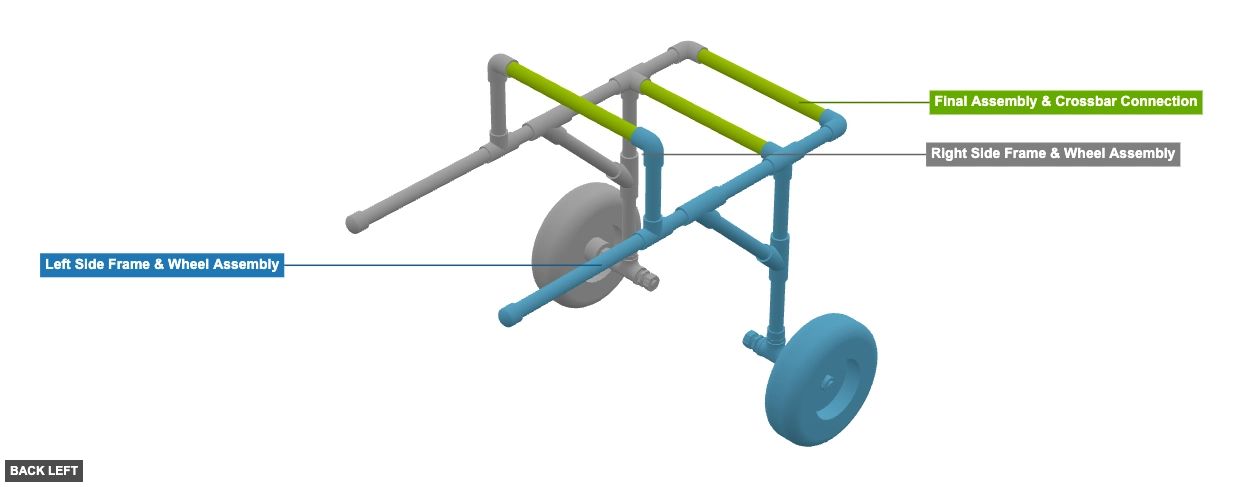
This assembly forms the left side of the wheelchair. It will be connected to the Right Side Assembly (Group 2) using the Crossbars (Group 3).
Forms the complete right side structure including the wheel, lower frame, upper supports, and connection points.
This assembly forms the right side of the wheelchair. It will be connected to the Left Side Assembly (Group 1) using the Crossbars (Group 3).
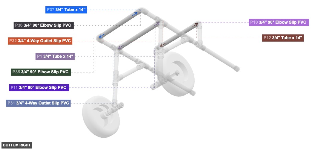
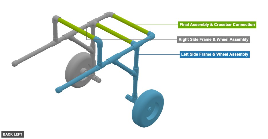
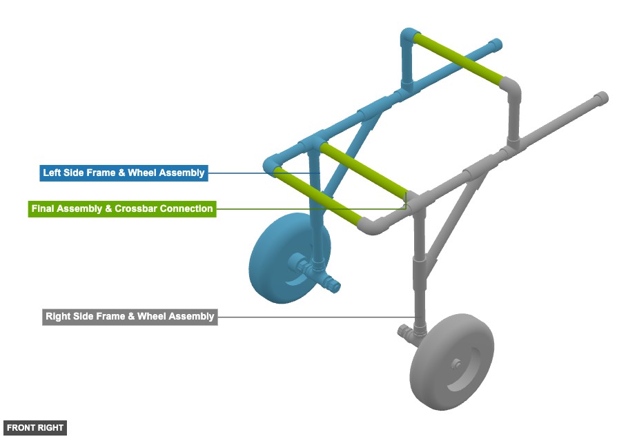
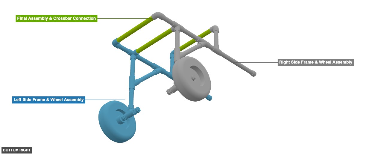
Connects the left and right side assemblies using crossbars to form the complete wheelchair frame.
This step completes the main structure of the dog wheelchair.