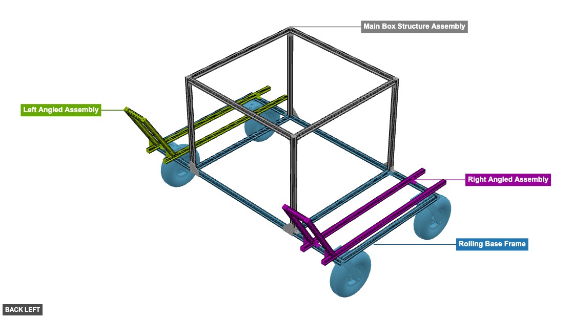
A four-wheeled utility cart constructed from T-slot aluminum extrusions (80/20). It features a main rectangular frame, a raised box structure, and two angled support assemblies on the sides. - Aluminum Utility Cart

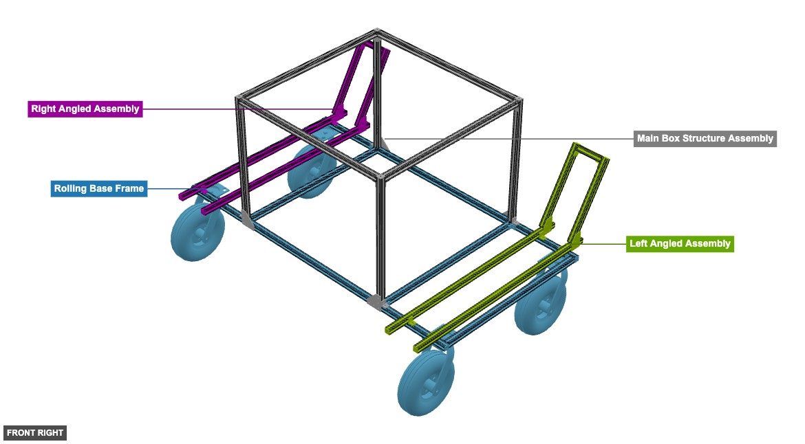
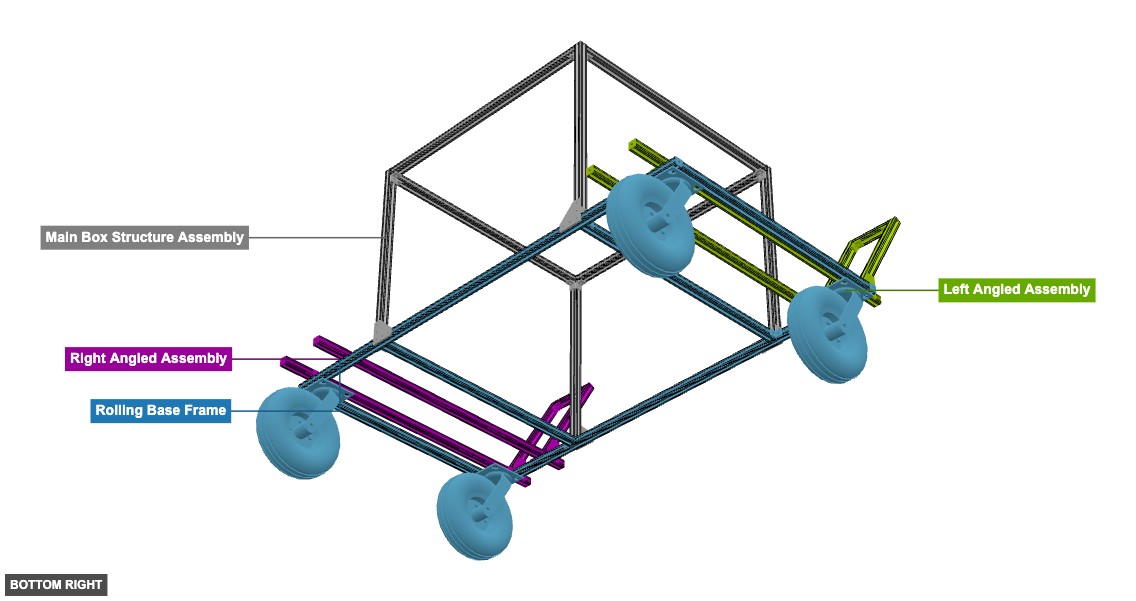
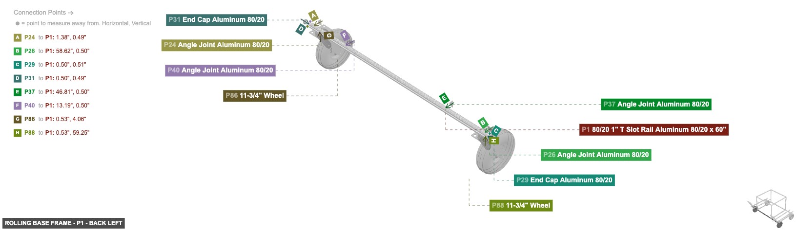
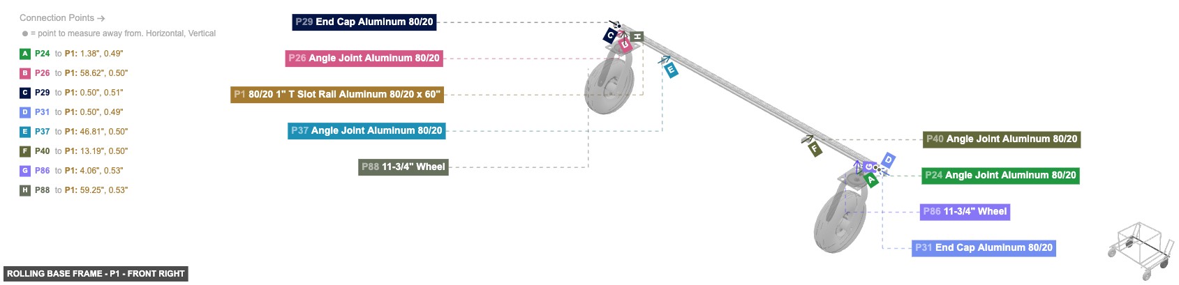
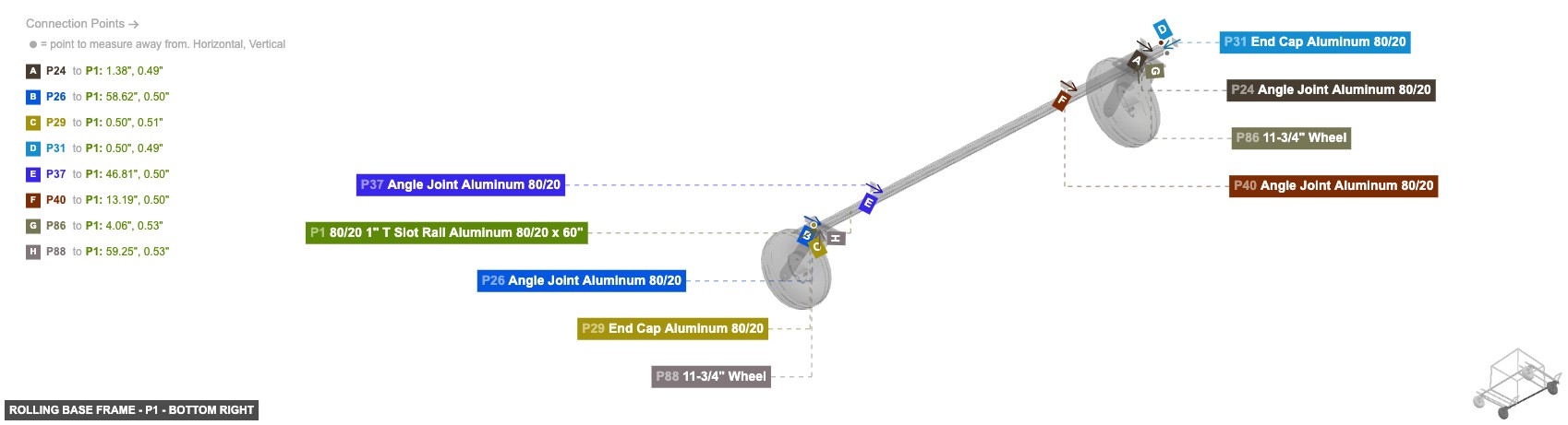
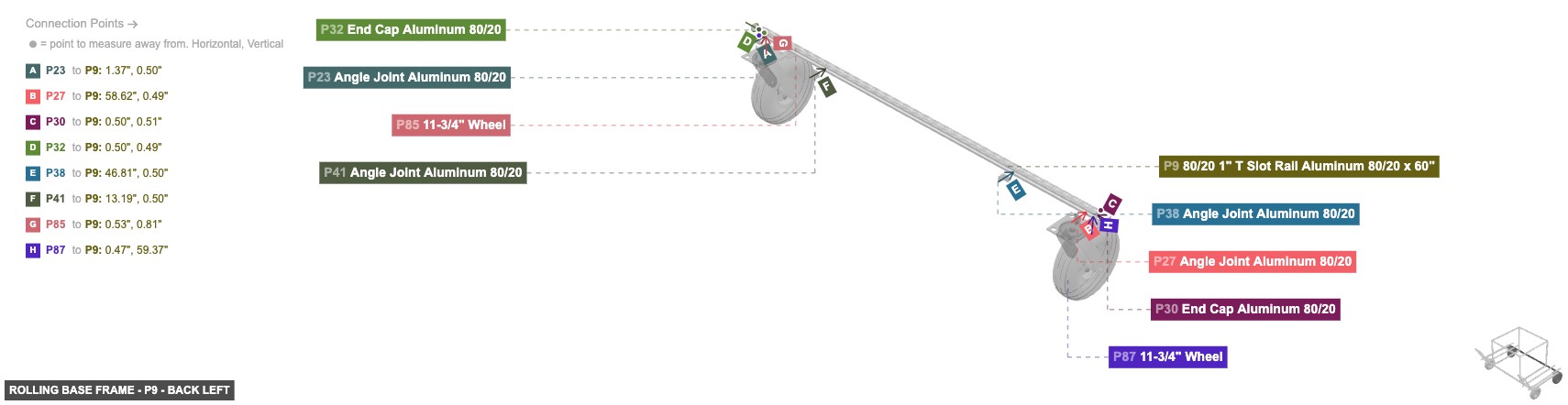
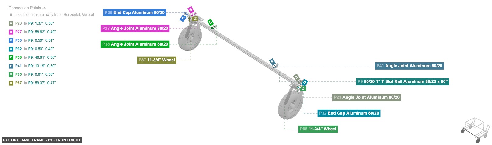
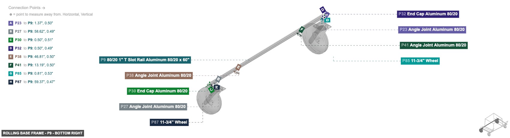
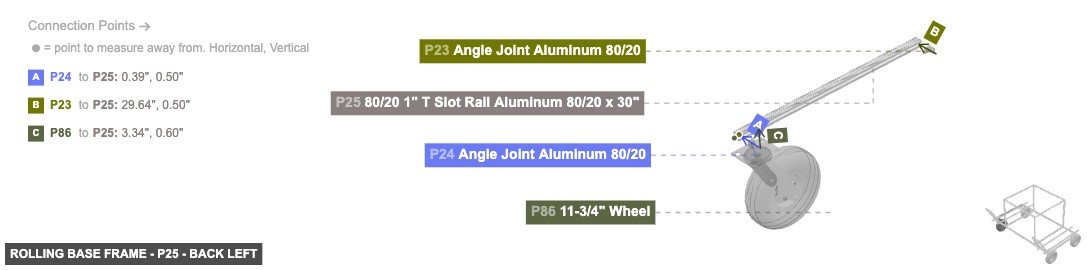
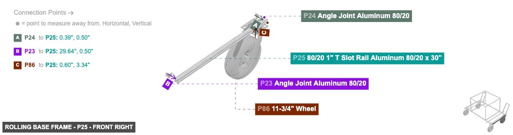
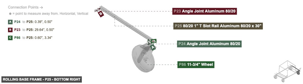
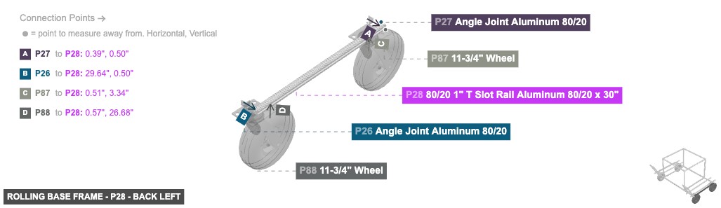
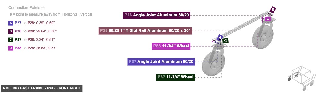
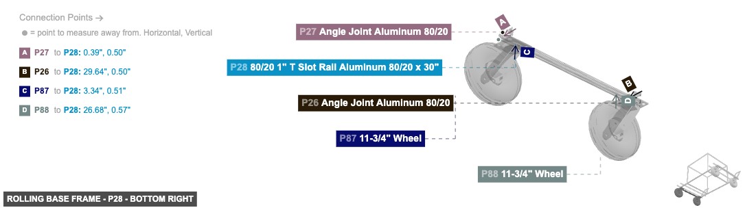
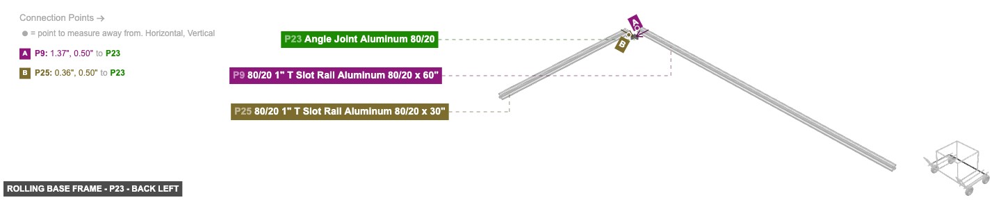
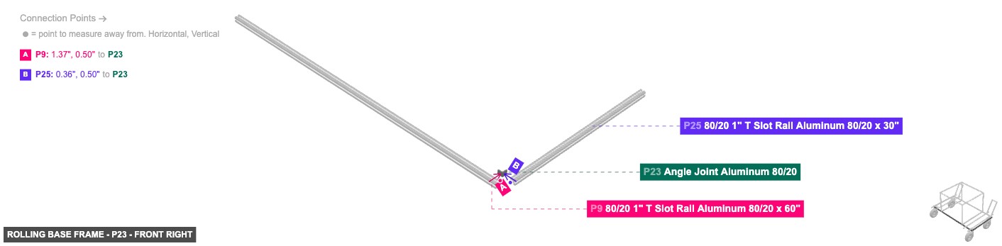
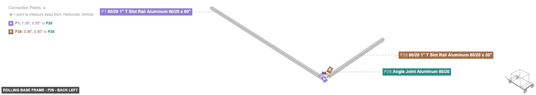
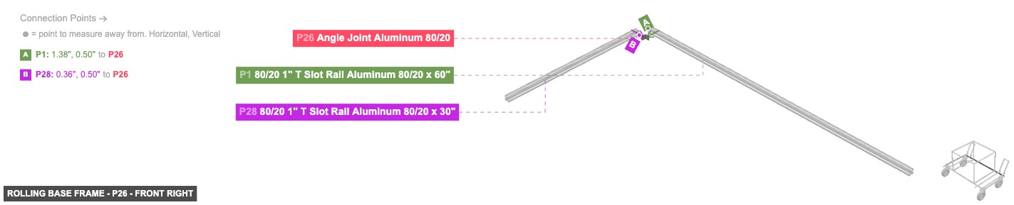
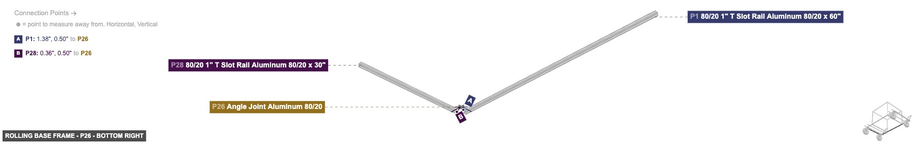
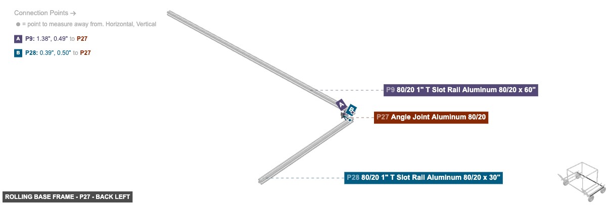
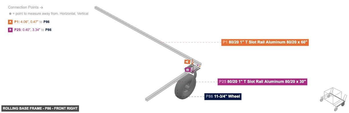
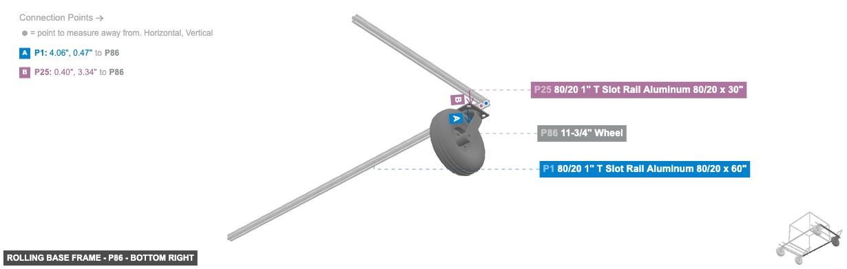
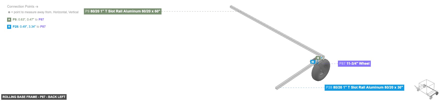
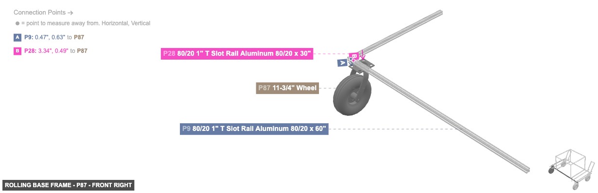
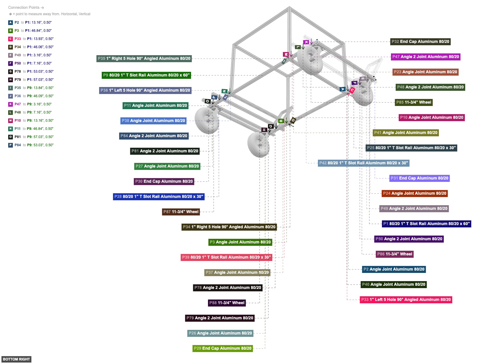
Forms the bottom foundation of the cart and includes the wheels.
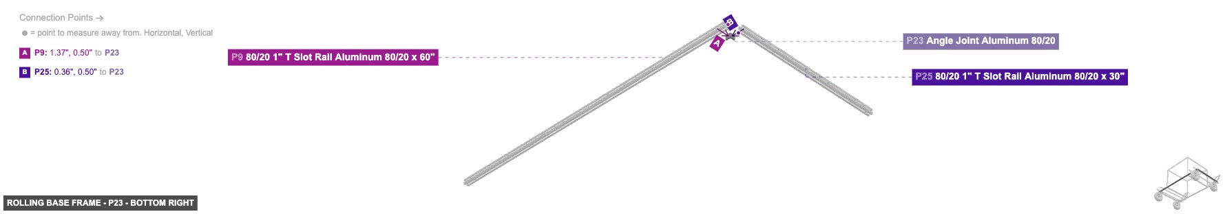
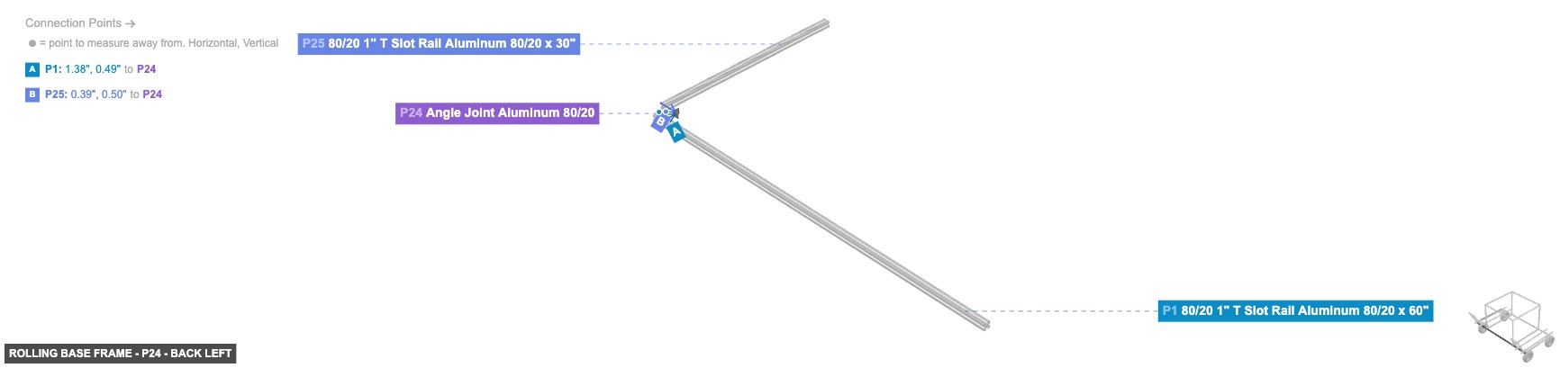
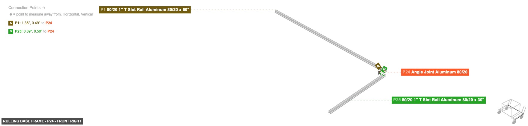
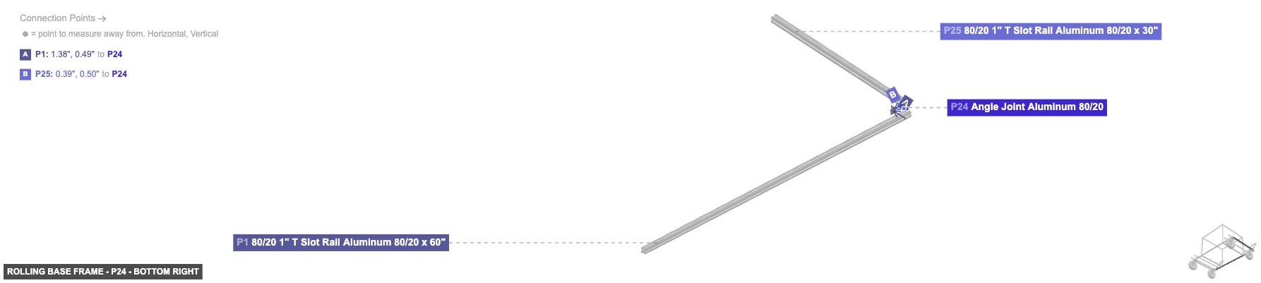
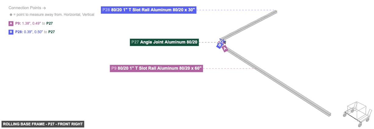
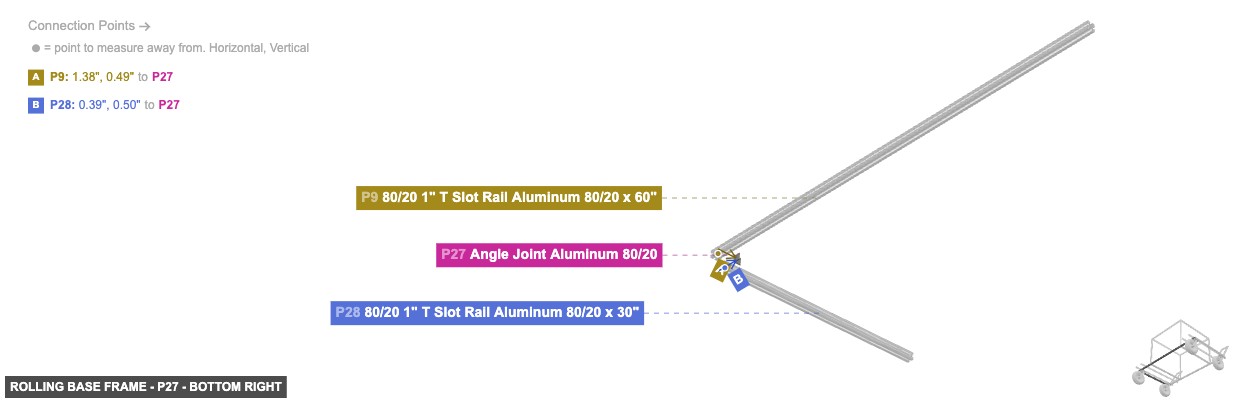
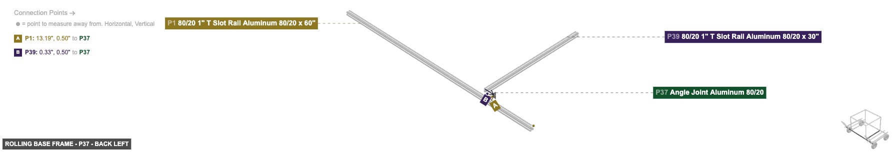
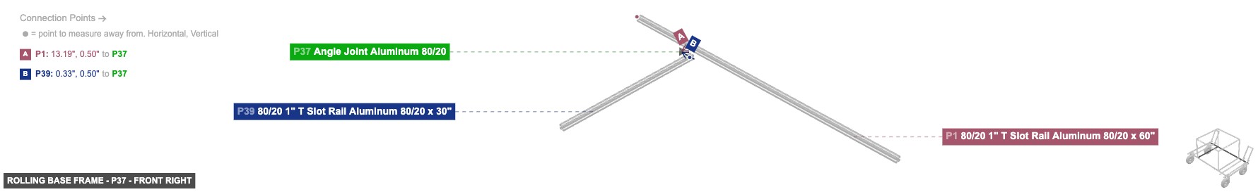
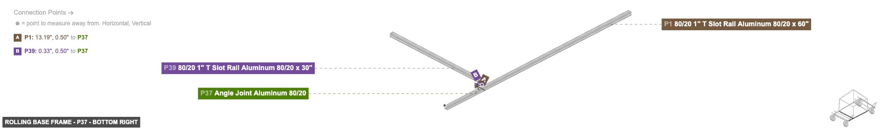
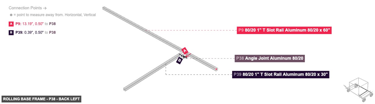
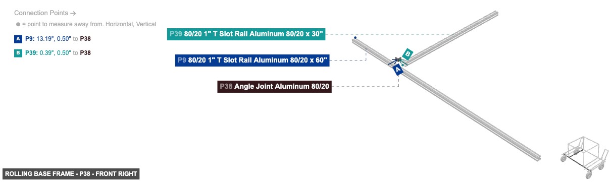
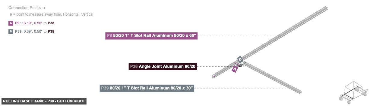
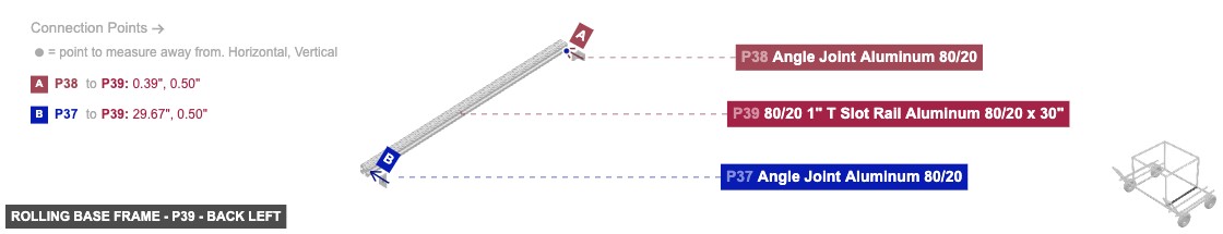
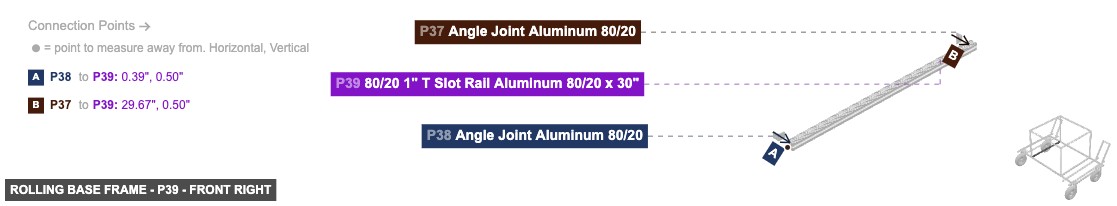
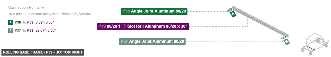
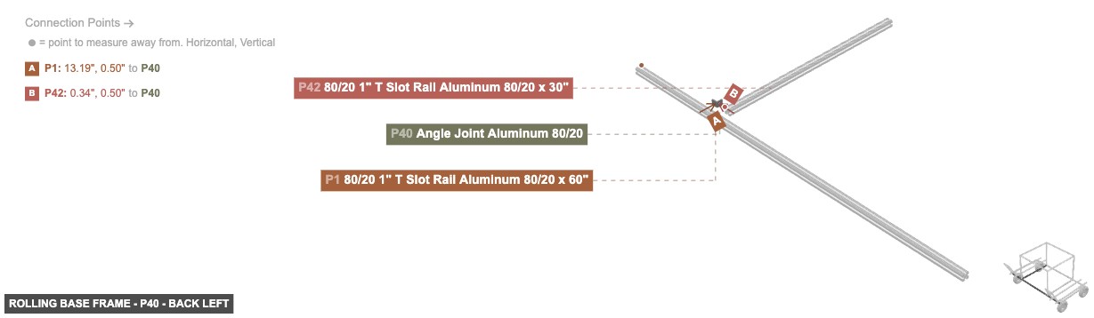
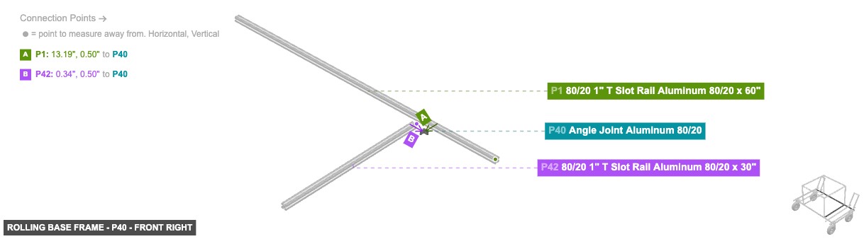
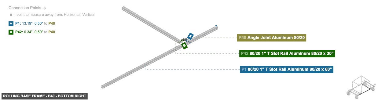
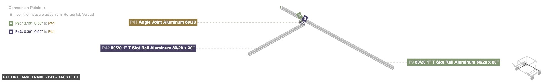
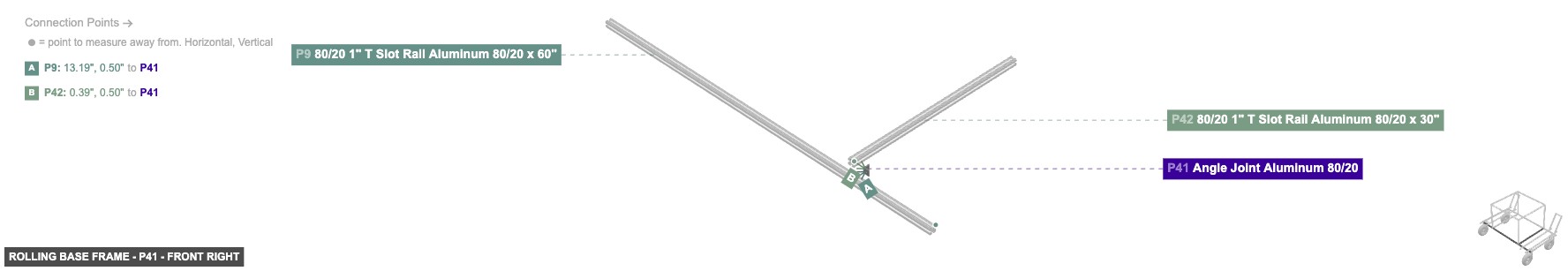
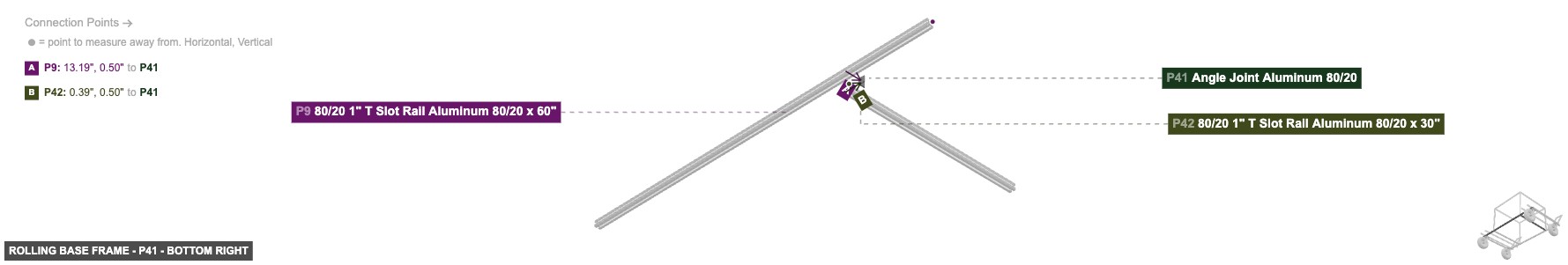
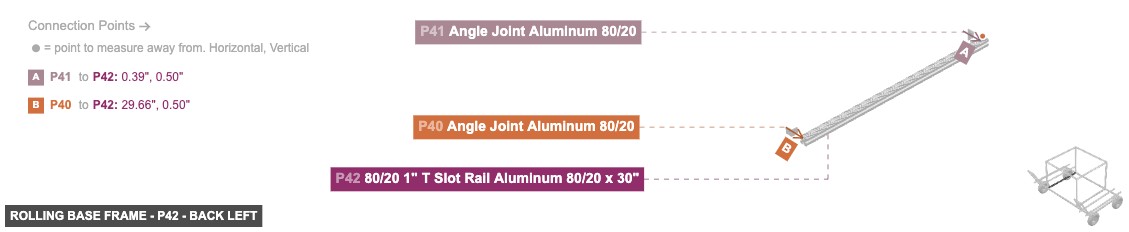
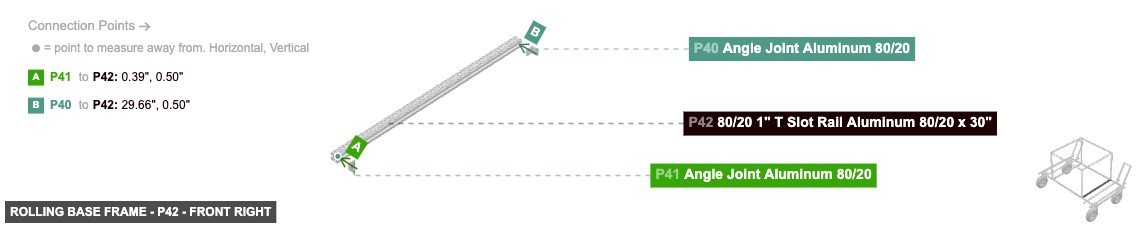
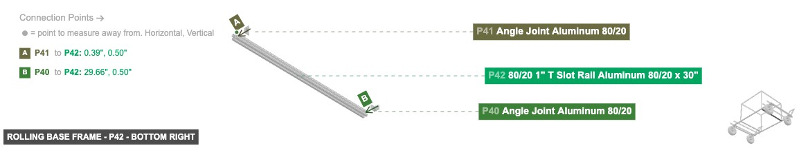
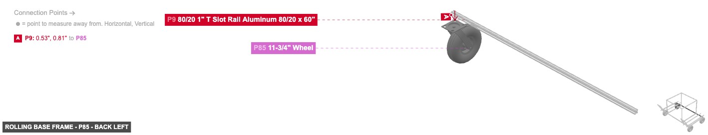
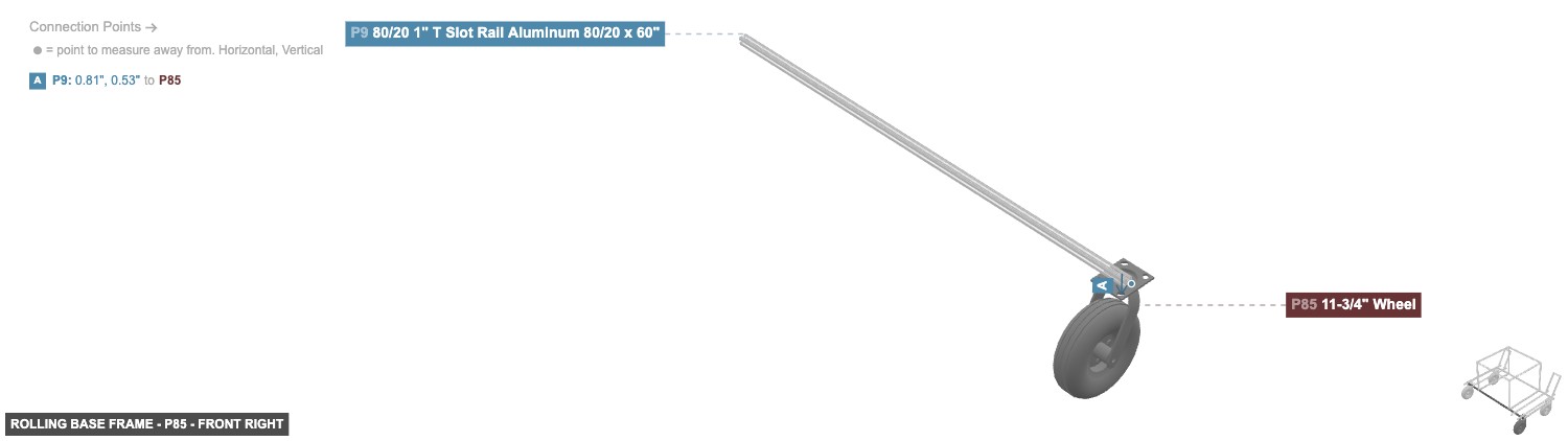
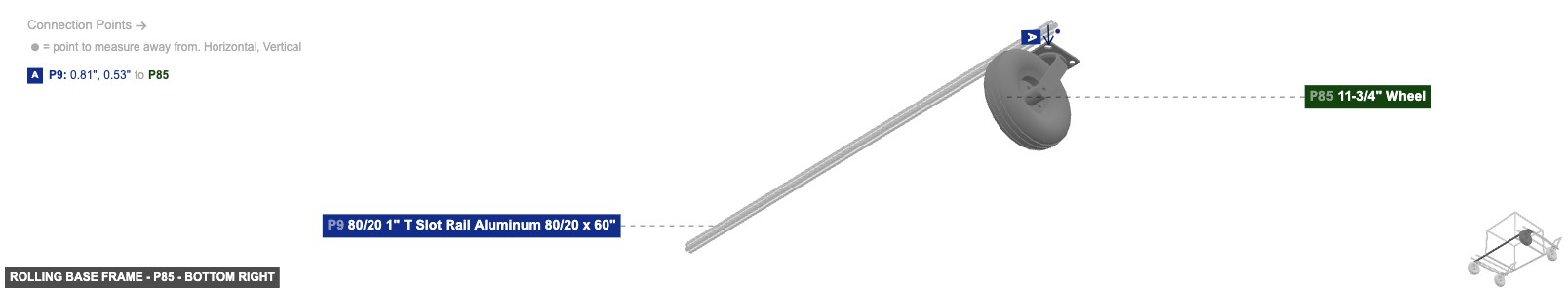
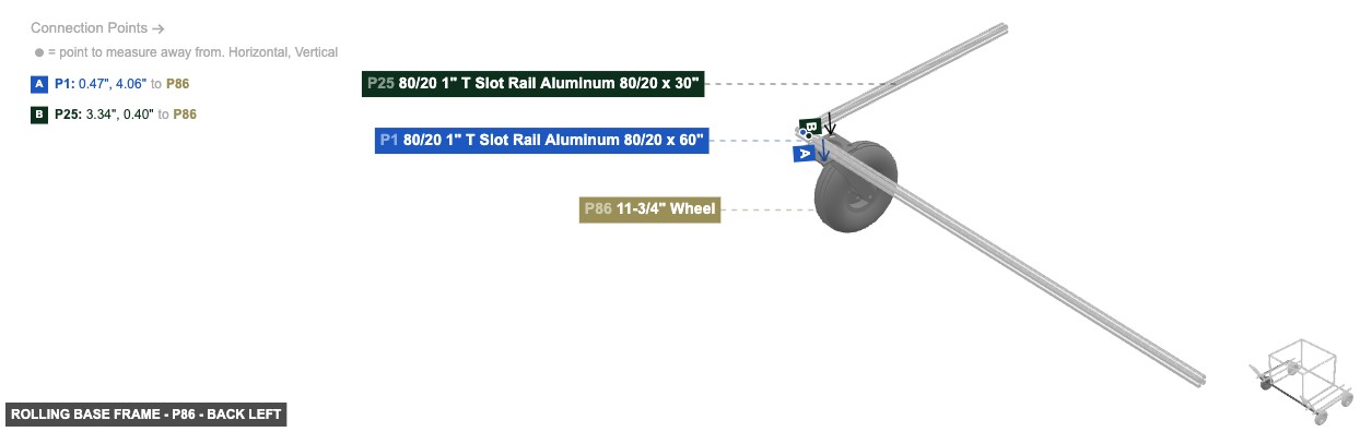
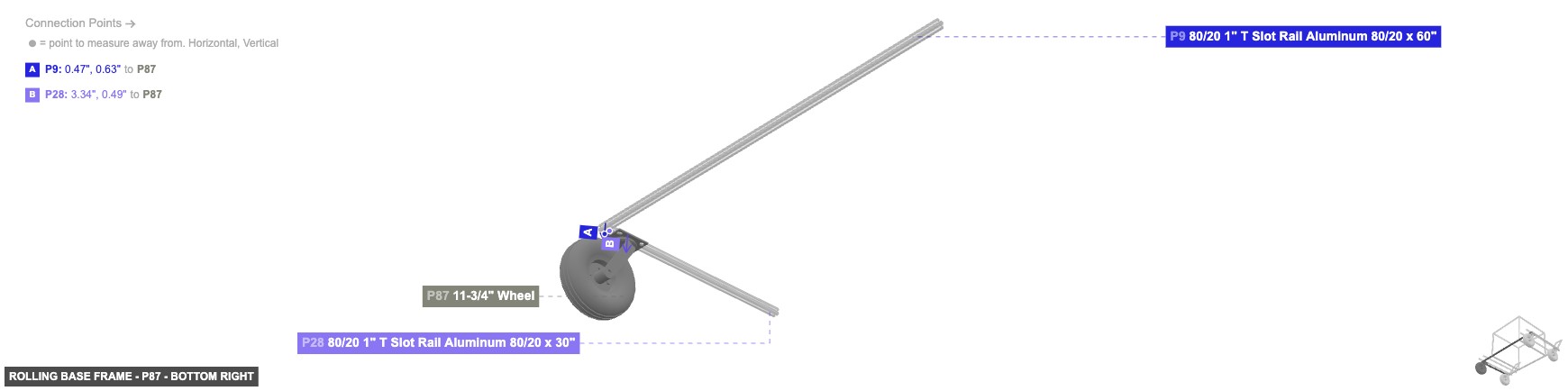
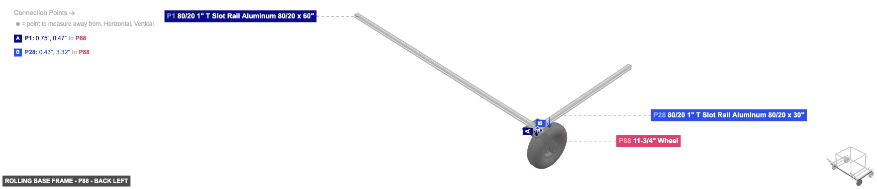
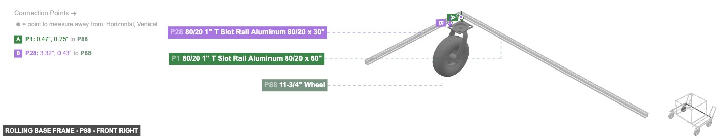
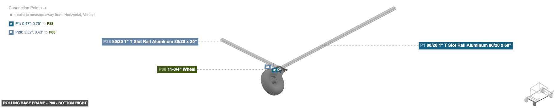
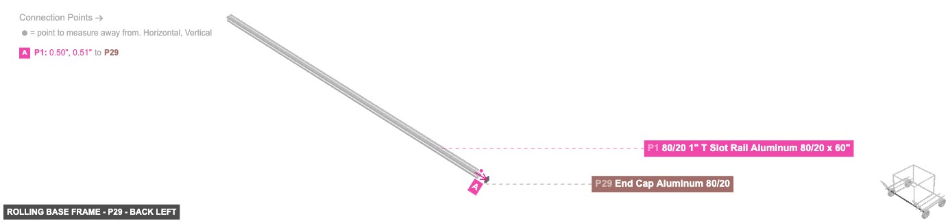
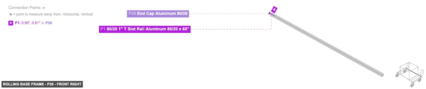
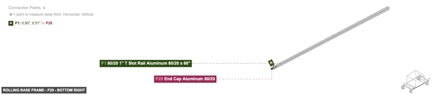
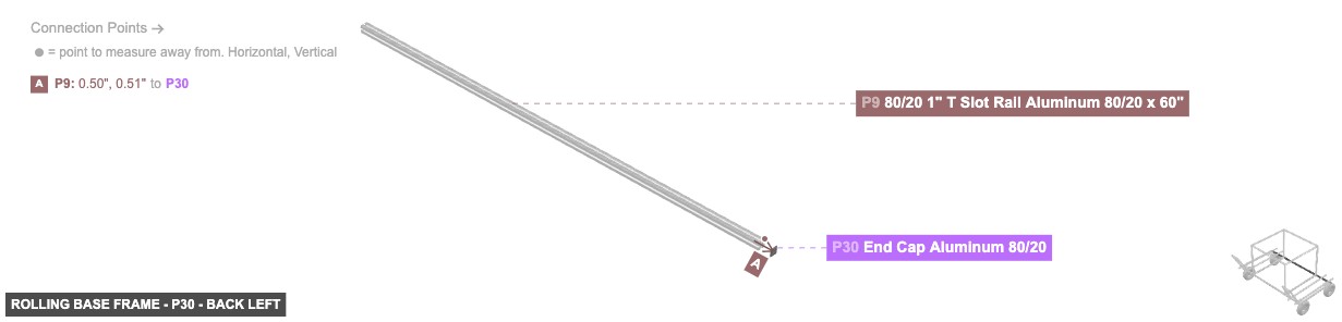
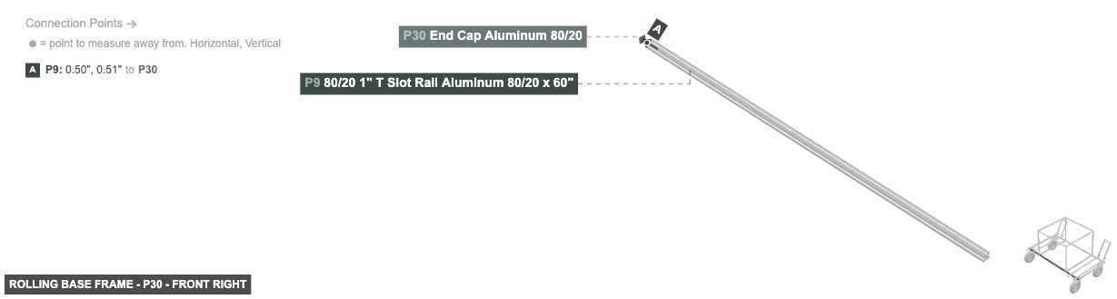
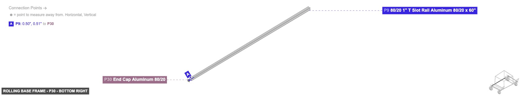
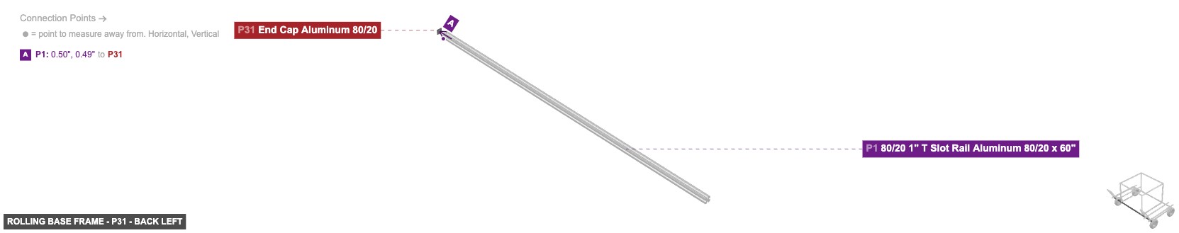
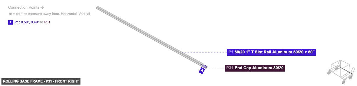
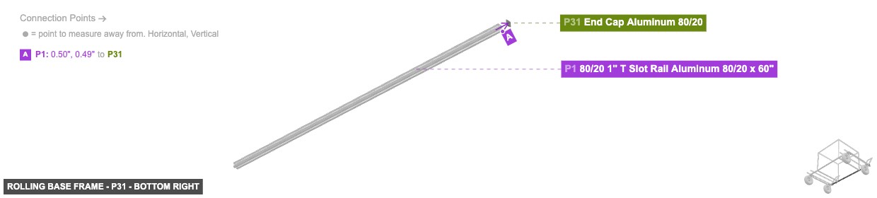
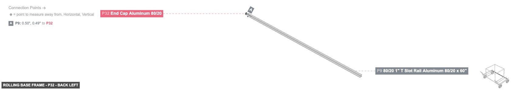
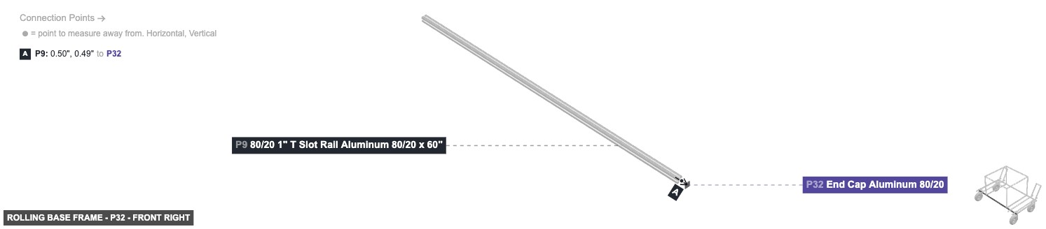
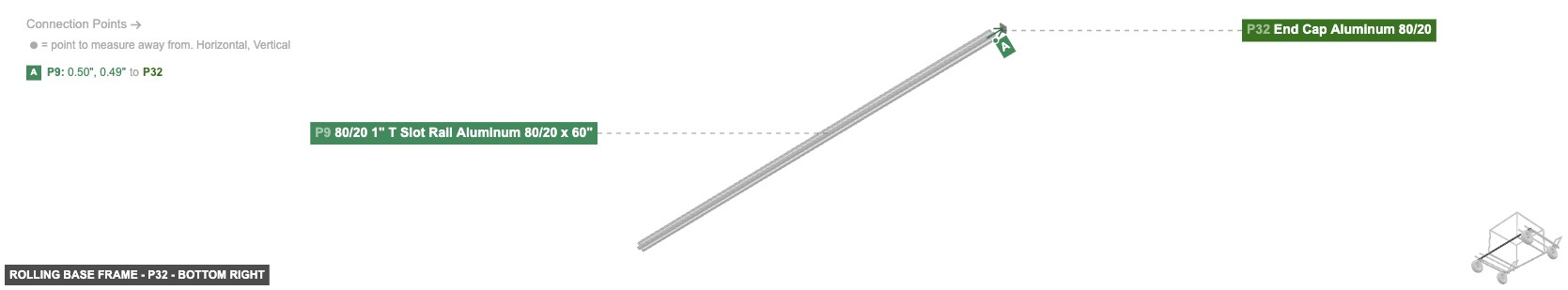
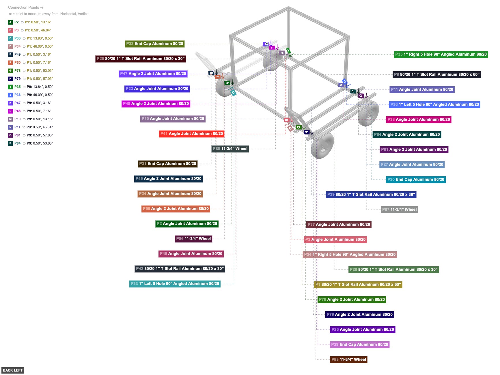
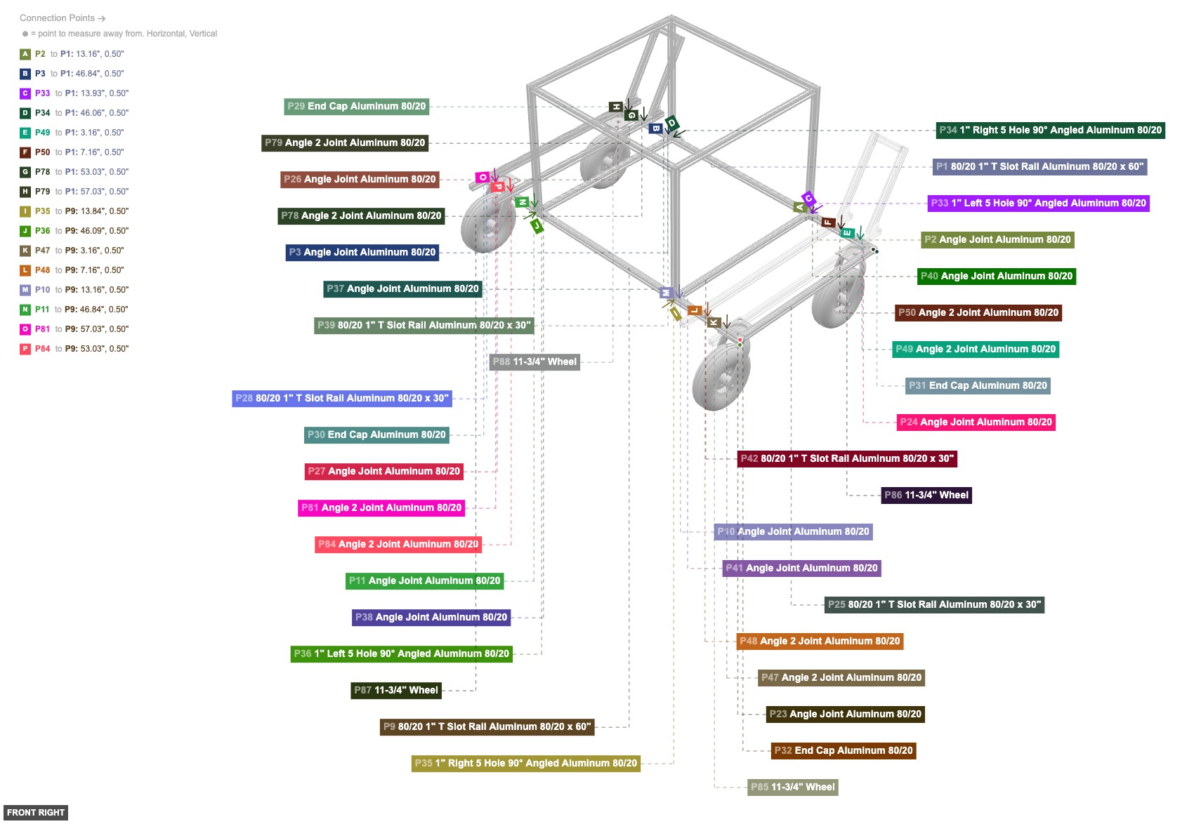
1. Form the main rectangle: Connect P1 (60" Rail) to P25 (30" Rail) using P24 (Angle Joint). Connect P1 to P28 (30" Rail) using P26 (Angle Joint). Connect P9 (60" Rail) to P25 using P23 (Angle Joint). Connect P9 to P28 using P27 (Angle Joint). 2. Attach intermediate rails: Connect P39 (30" Rail) between P1 and P9 using P37 (Angle Joint) and P38 (Angle Joint). Connect P42 (30" Rail) between P1 and P9 using P40 (Angle Joint) and P41 (Angle Joint). 3. Attach wheels: Connect P86 (Wheel) to the bottom rails of P1 and P25. Connect P88 (Wheel) to the bottom rails of P1 and P28. Connect P85 (Wheel) to the bottom rail of P9. Connect P87 (Wheel) to the bottom rails of P9 and P28. 4. Add end caps: Attach P31 (End Cap) and P29 (End Cap) to the ends of P1. Attach P32 (End Cap) and P30 (End Cap) to the ends of P9.
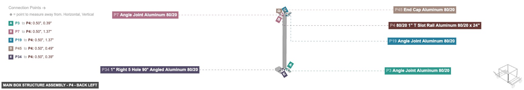
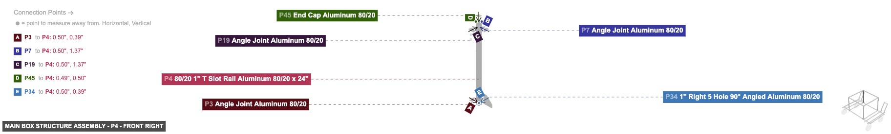
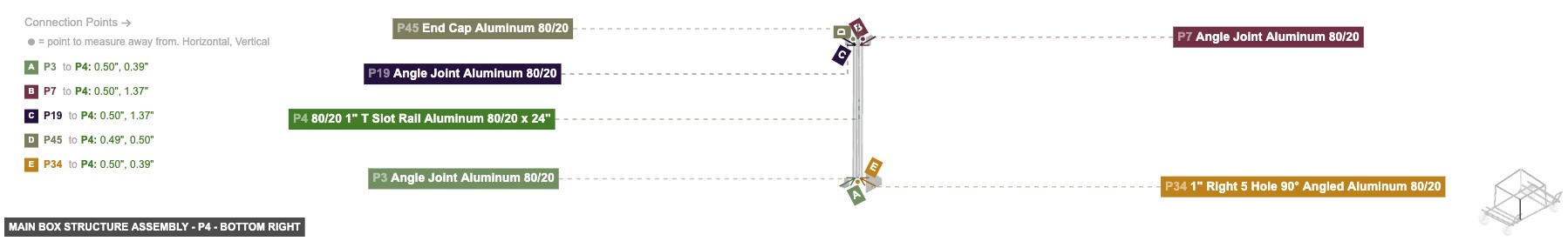
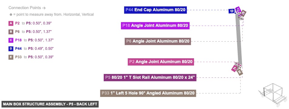
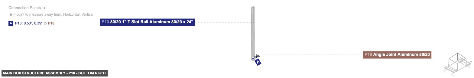
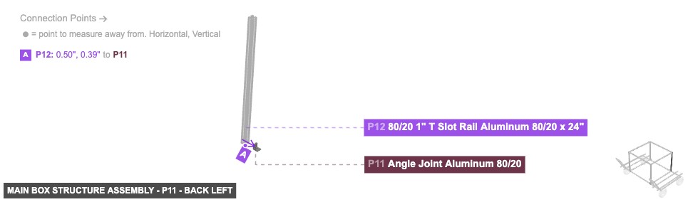
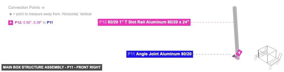
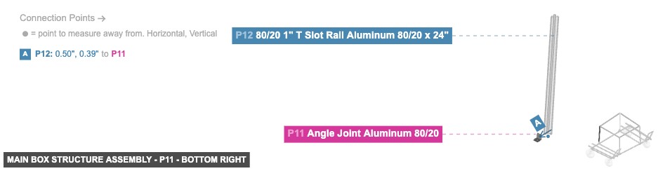
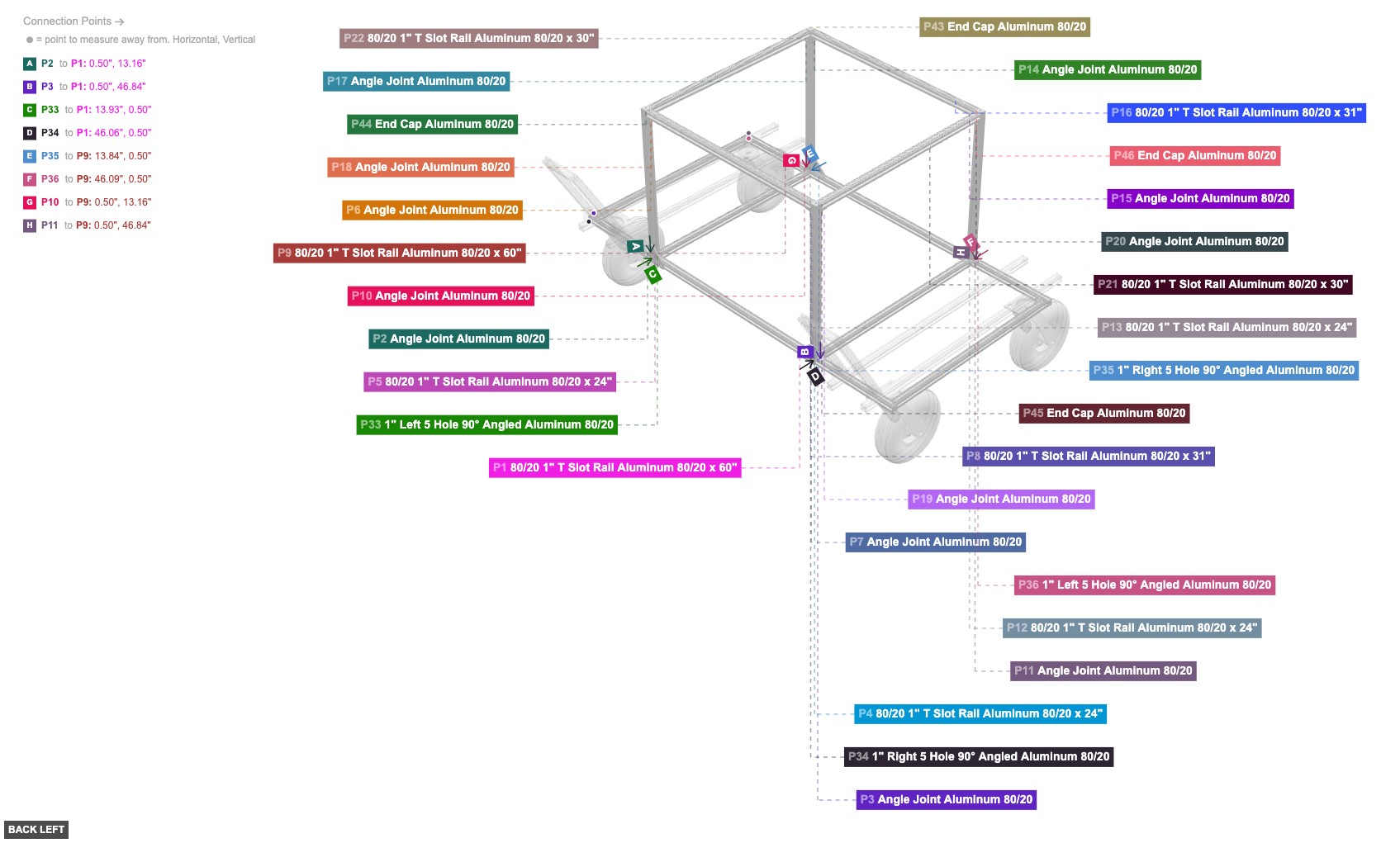
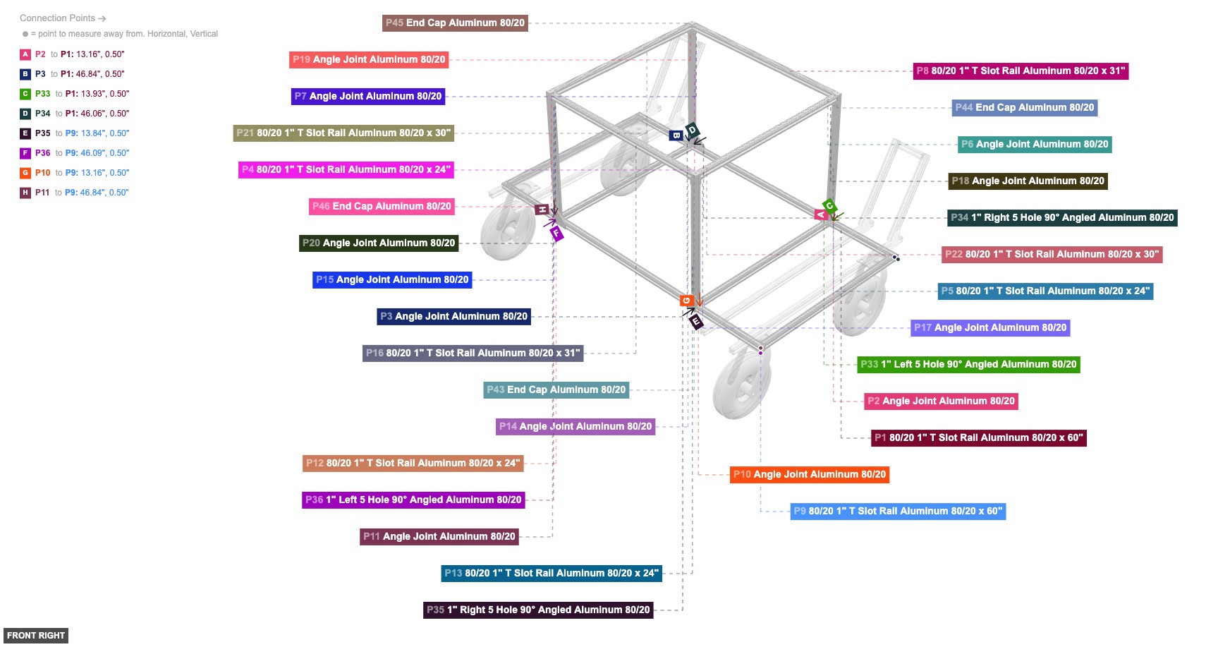
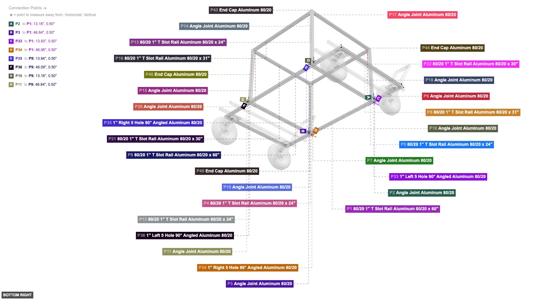
Creates the upper storage area and connects it to the base.
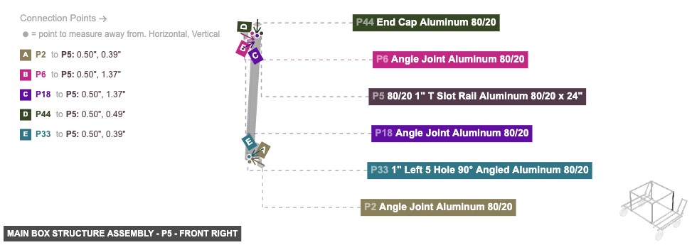
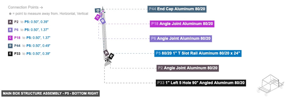
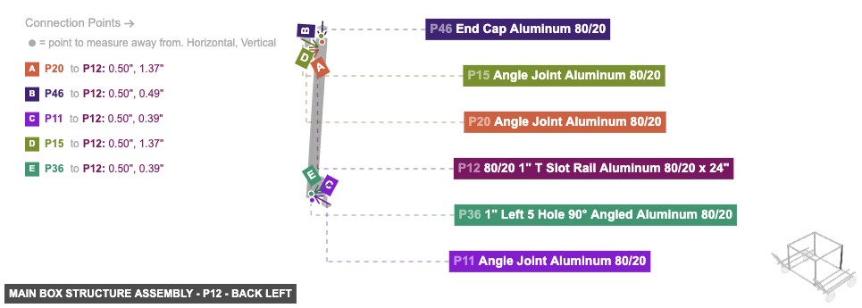
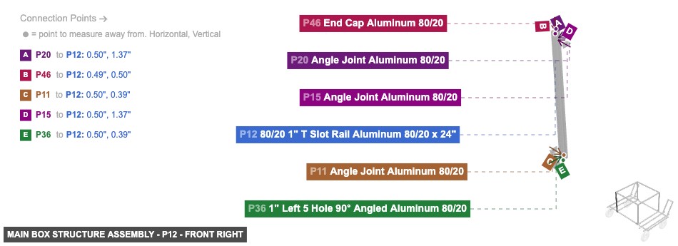
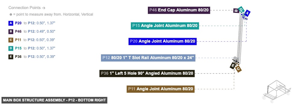
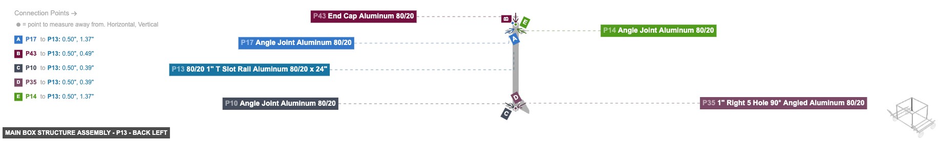
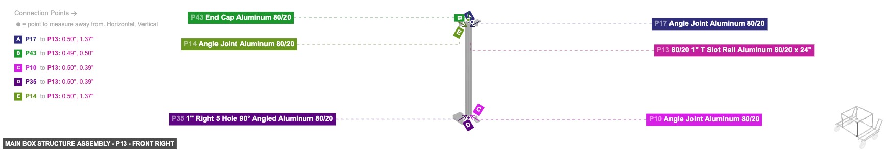
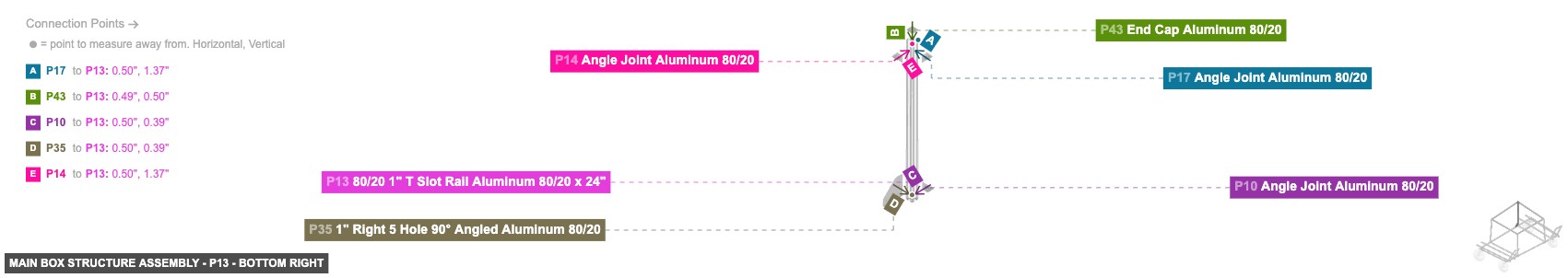
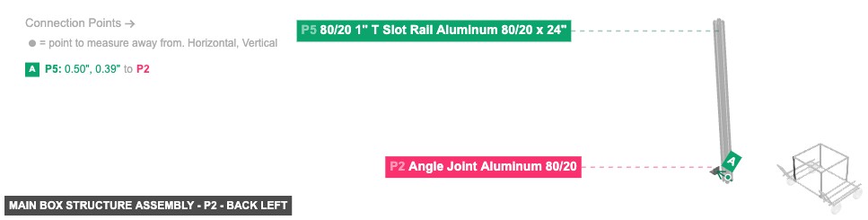
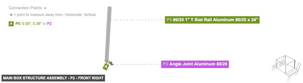
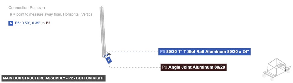
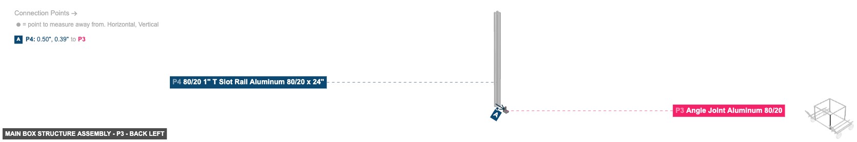
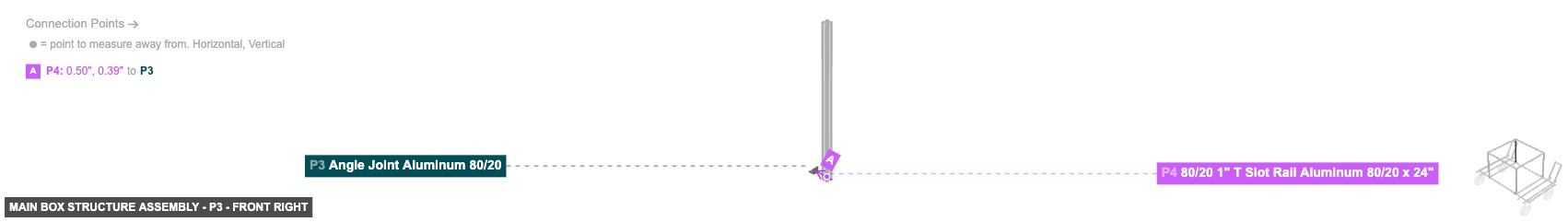
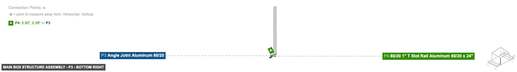
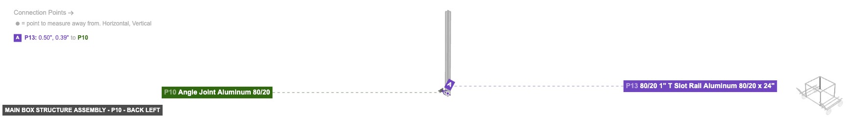
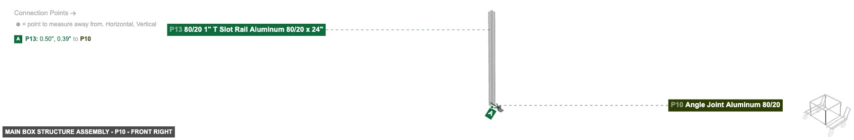
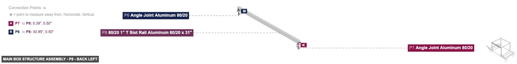
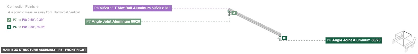
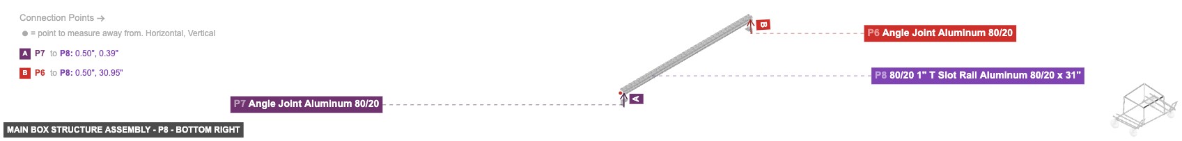
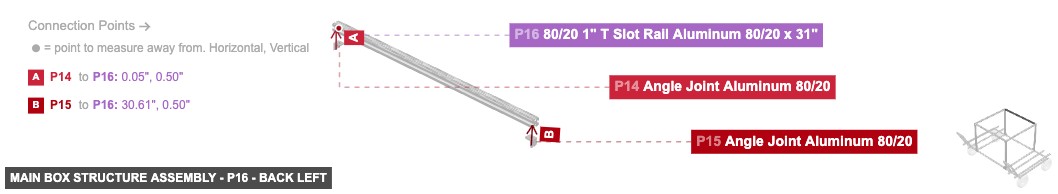
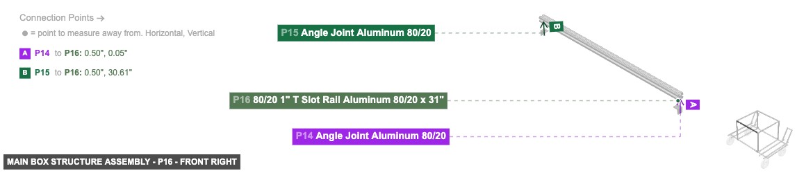
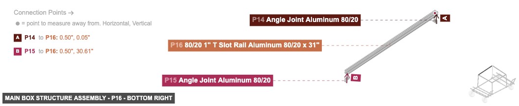
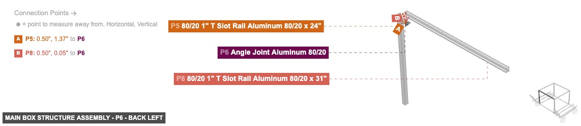
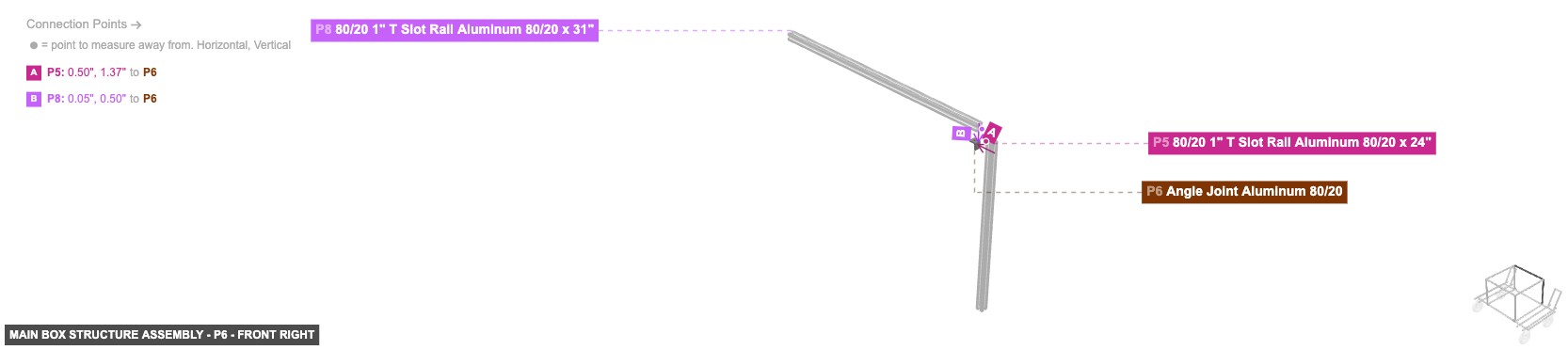
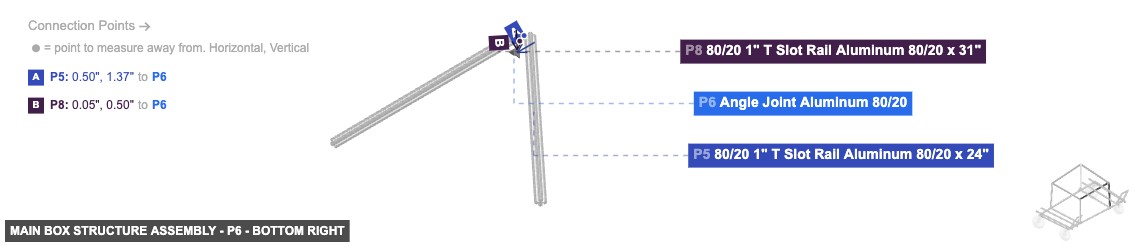
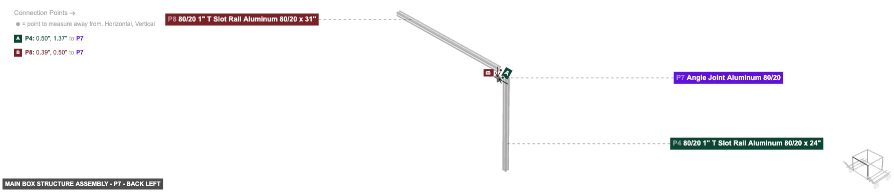
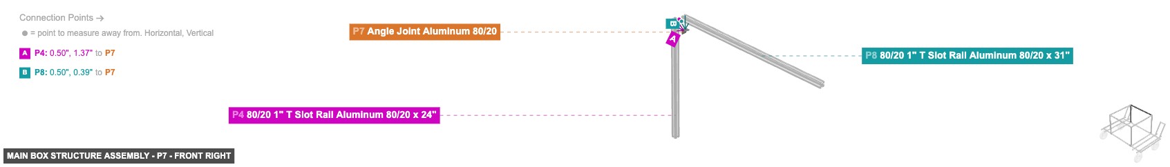
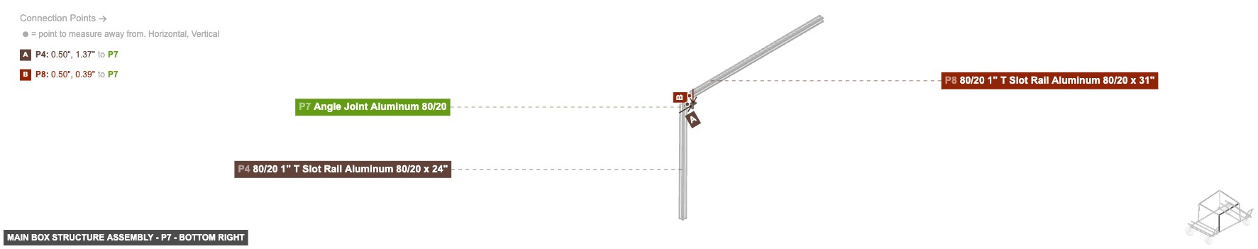
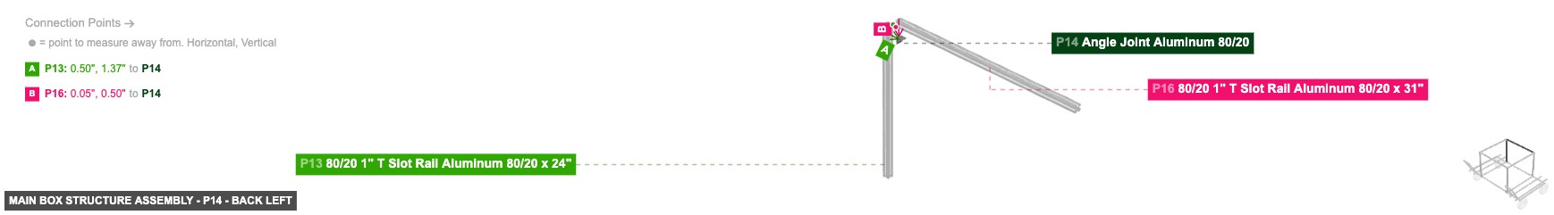
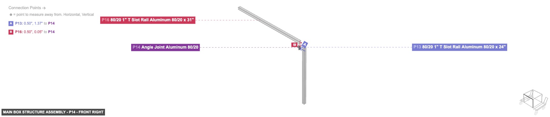
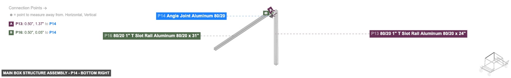
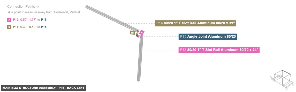
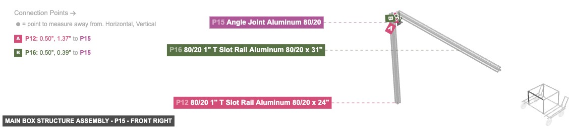
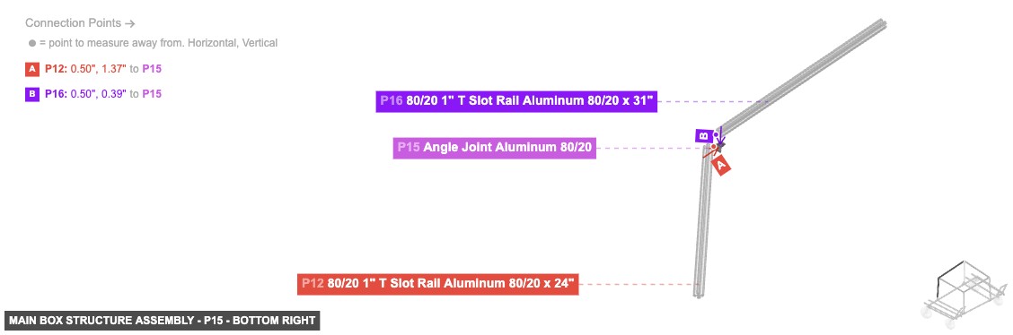
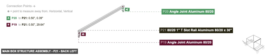
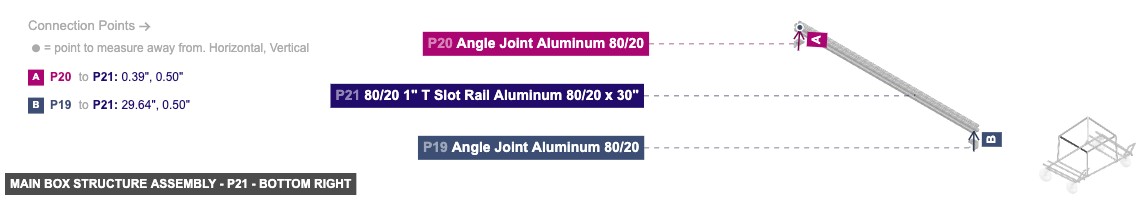
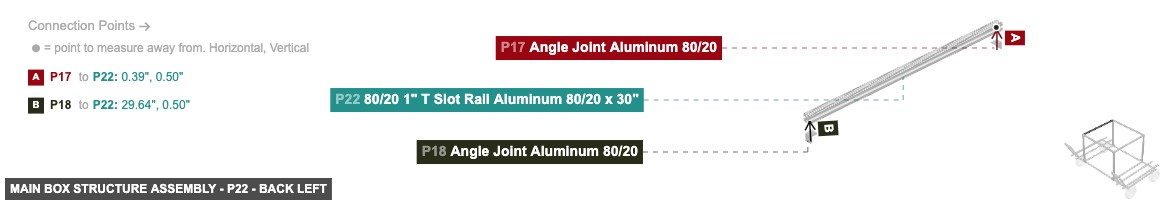
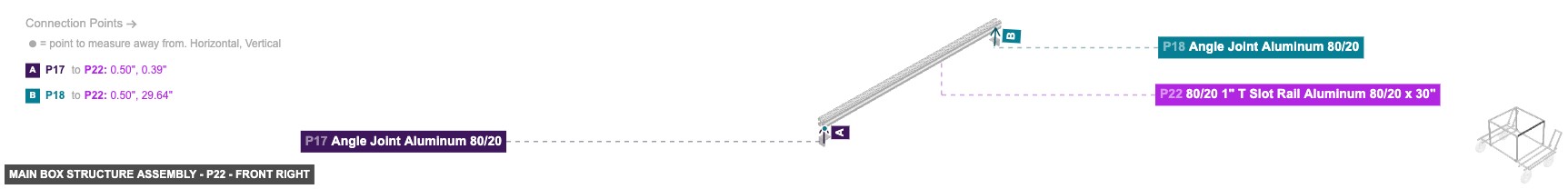
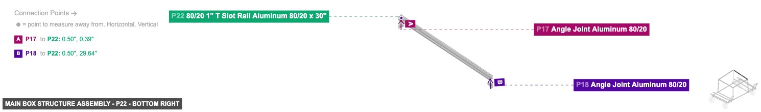
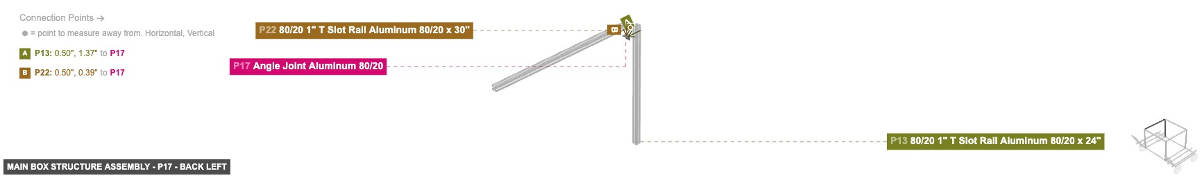
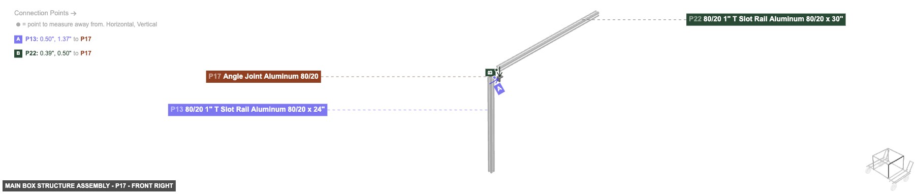
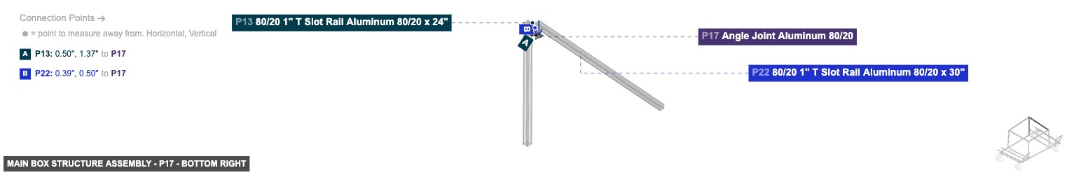
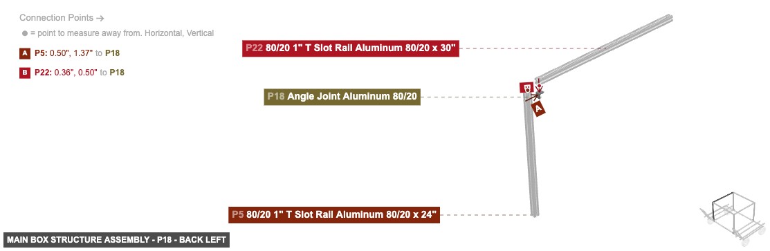
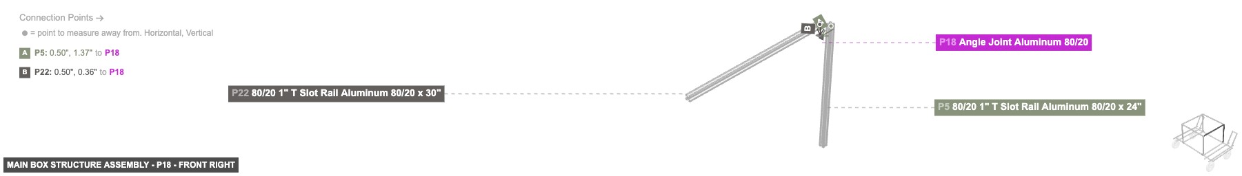
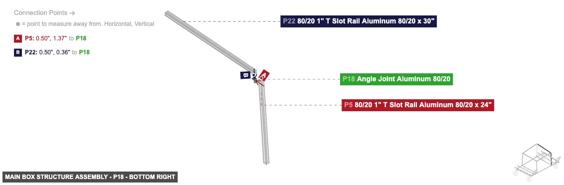
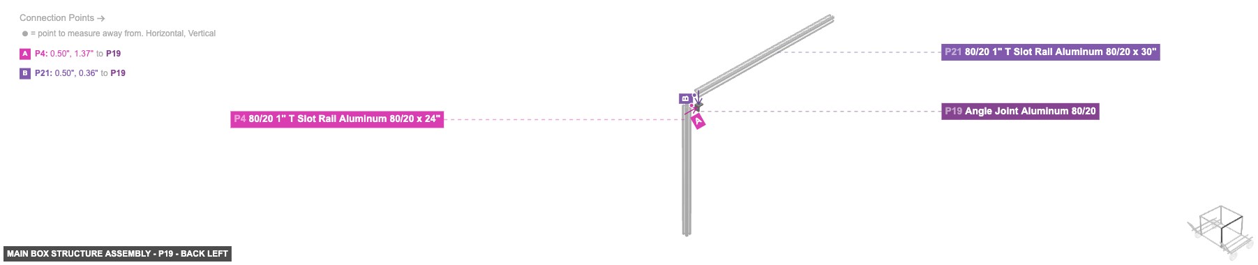
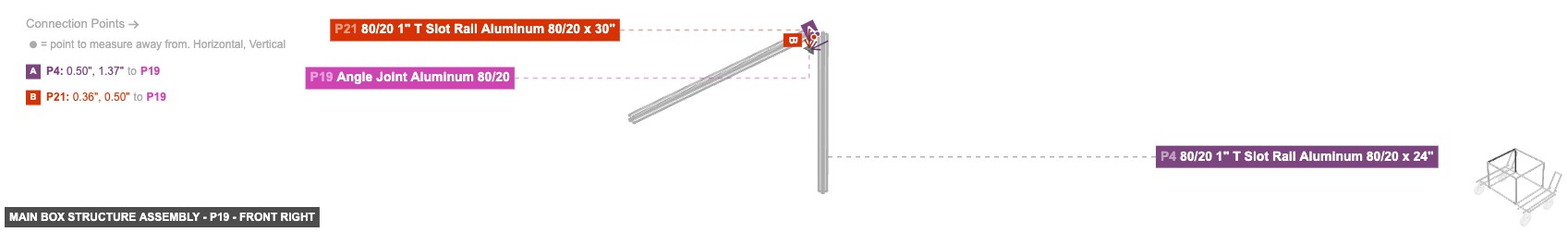
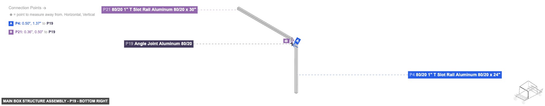
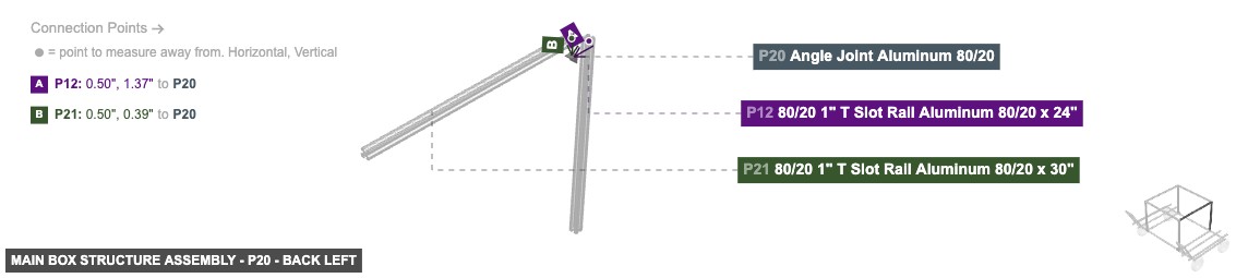
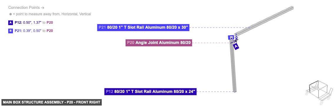
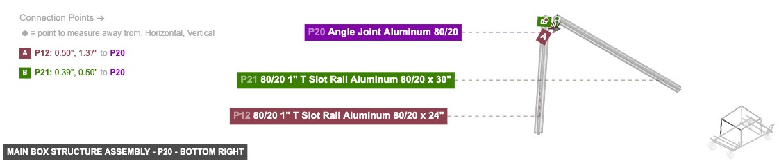
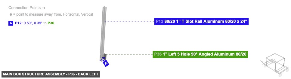
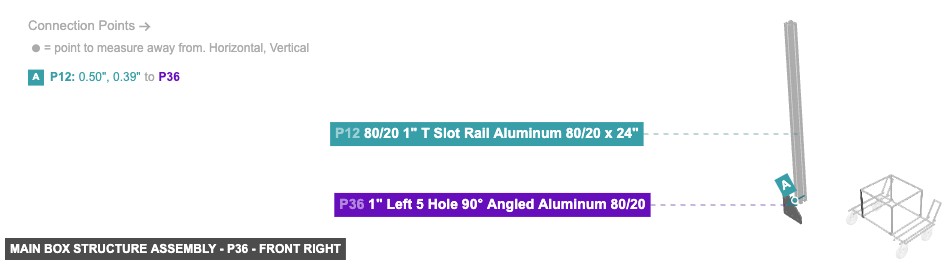
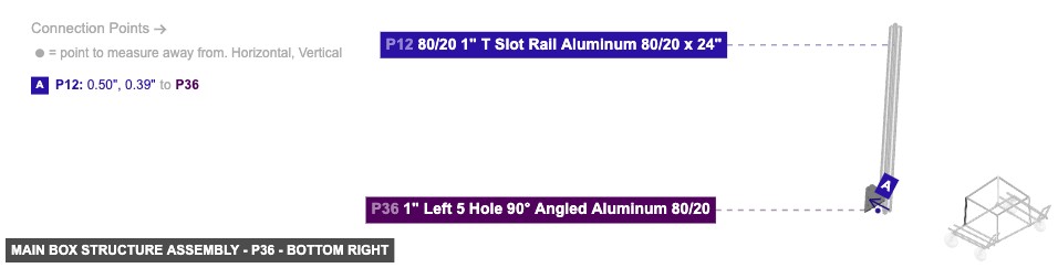
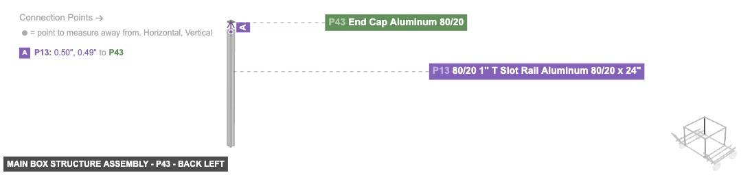
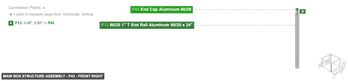
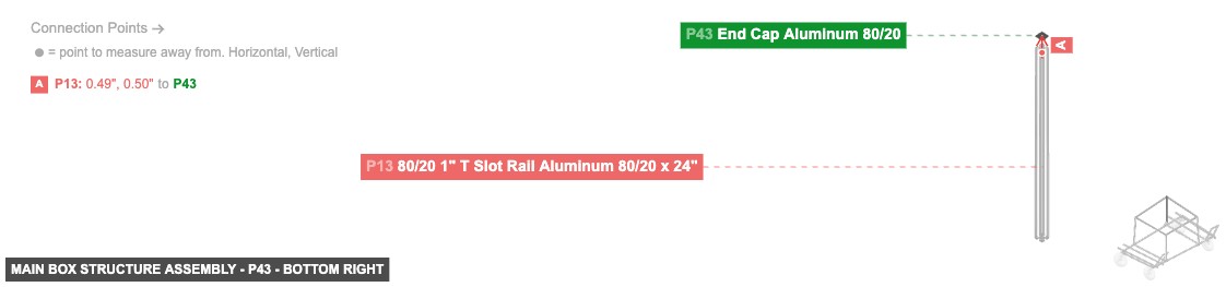
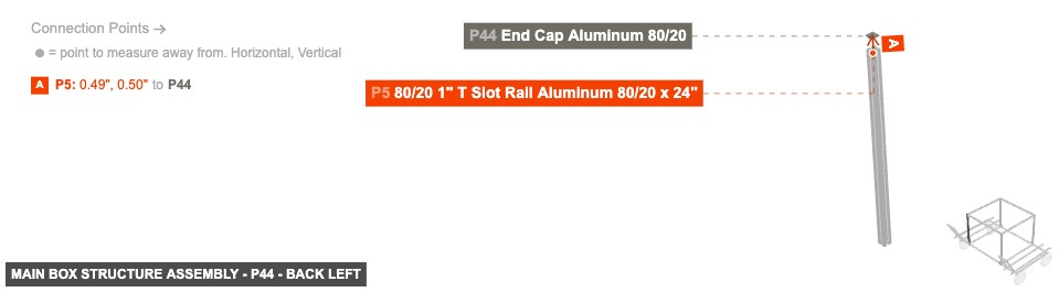
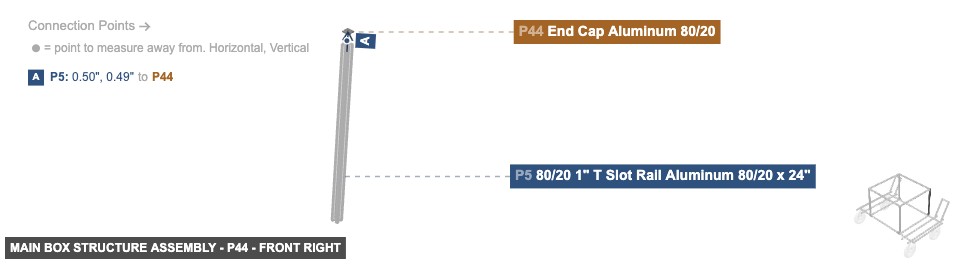
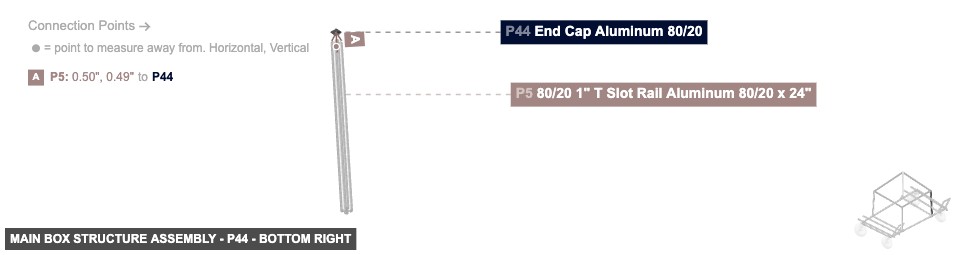
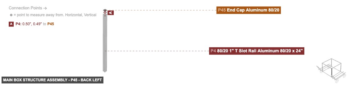
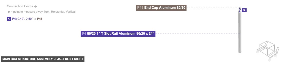
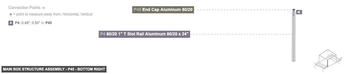
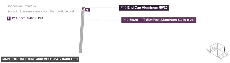
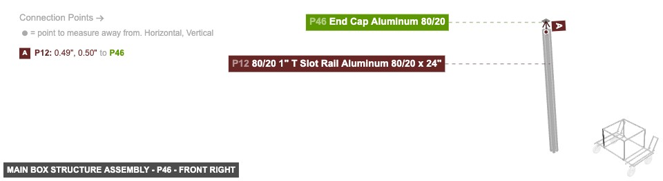
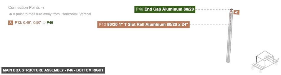
1. Assemble front top rail: Connect P8 (31" Rail) between P4 (24" Rail) (using P7 Angle Joint) and P5 (24" Rail) (using P6 Angle Joint). 2. Assemble rear top rail: Connect P16 (31" Rail) between P12 (24" Rail) (using P15 Angle Joint) and P13 (24" Rail) (using P14 Angle Joint). 3. Assemble side top rails: Connect P22 (30" Rail) between P5 (using P18 Angle Joint) and P13 (using P17 Angle Joint). Connect P21 (30" Rail) between P4 (using P19 Angle Joint) and P12 (using P20 Angle Joint). 4. Prepare vertical rails for connection: Attach the Male Rail of P2 (Angle Joint) to the Top Female Rail of P1. Attach the Male Rail of P3 (Angle Joint) to the Top Female Rail of P1. Attach the Male Rail of P10 (Angle Joint) to the Top Female Rail of P9. Attach the Male Rail of P11 (Angle Joint) to the Top Female Rail of P9. 5. Add end caps: Attach P44 (End Cap) to the top End Hole Female of P5. Attach P45 (End Cap) to the top End Hole Female of P4. Attach P43 (End Cap) to the top End Hole Female of P13. Attach P46 (End Cap) to the top End Hole Female of P12.

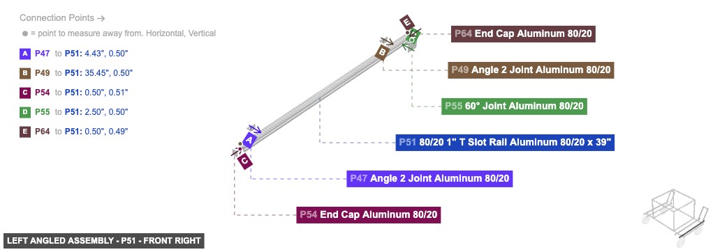
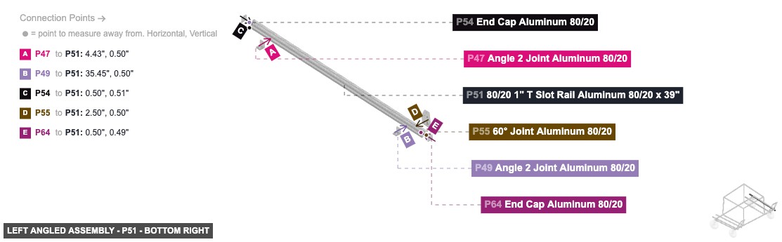
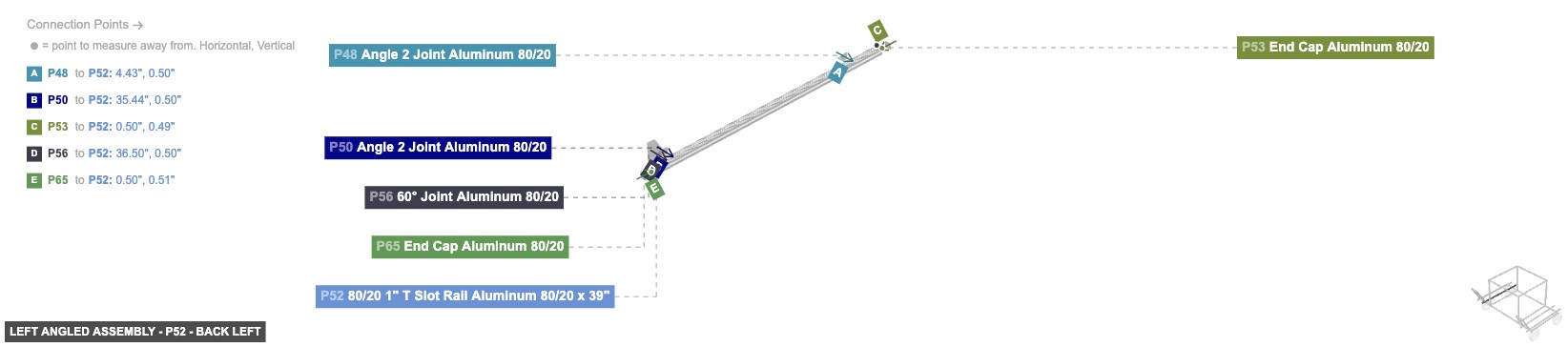
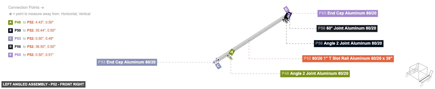
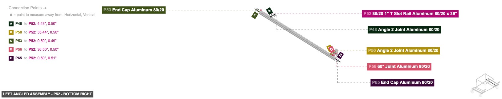
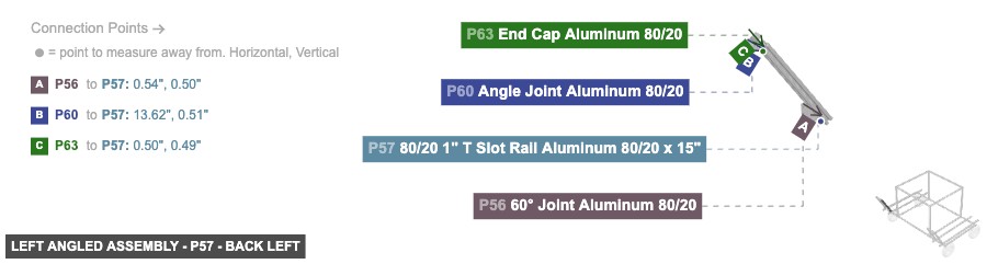
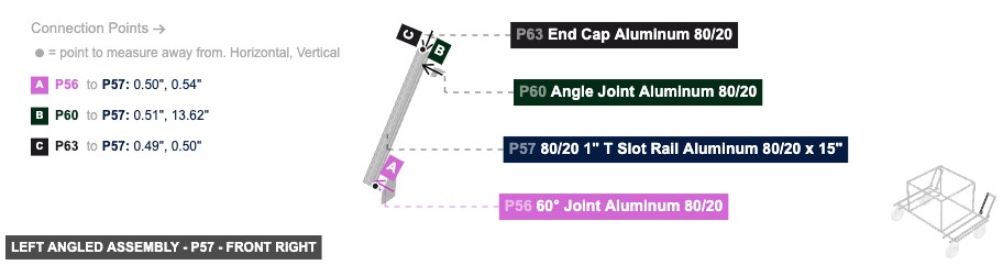
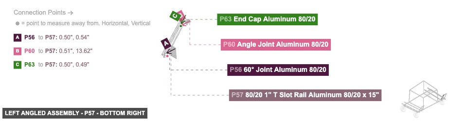
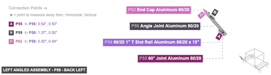
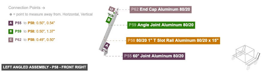
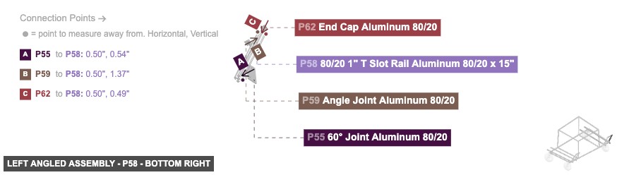
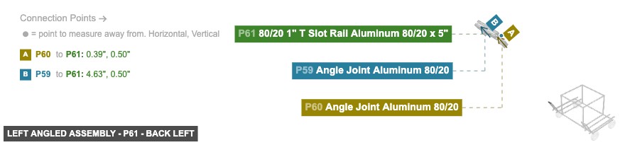
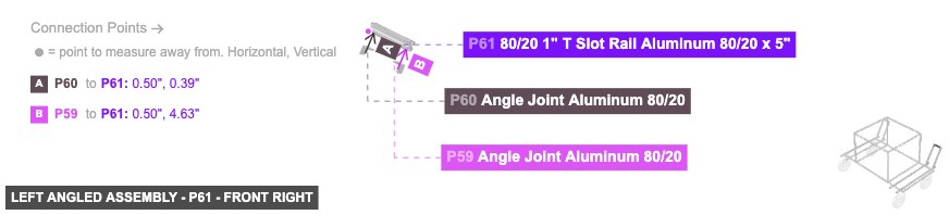
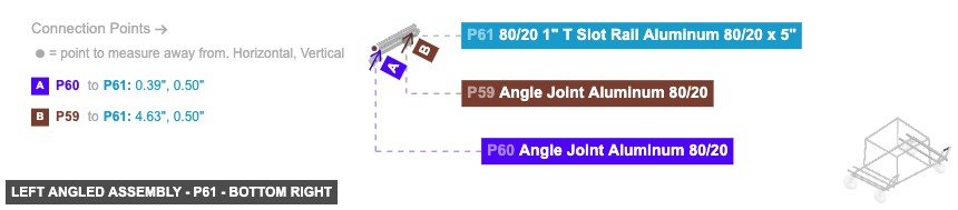
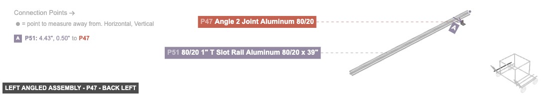
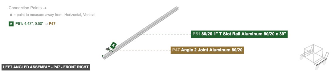
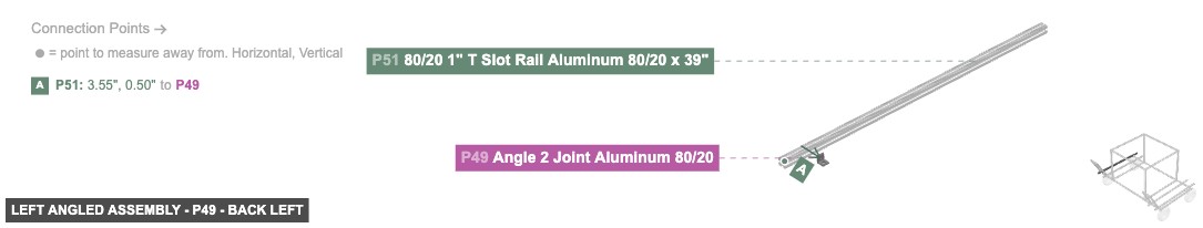
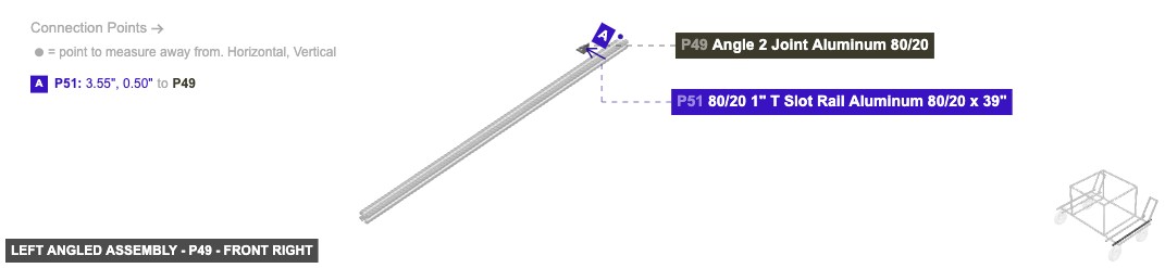
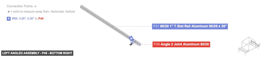
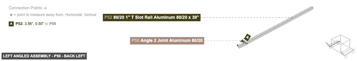
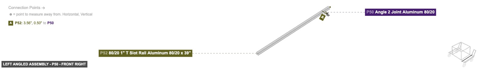
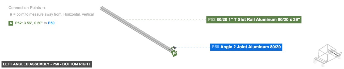
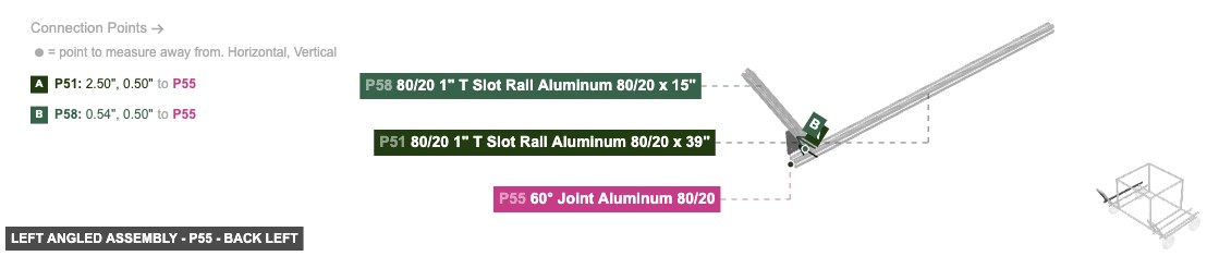
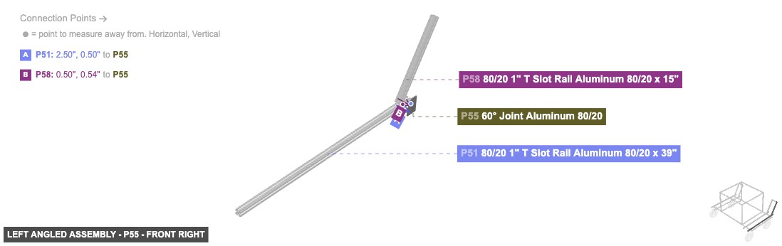
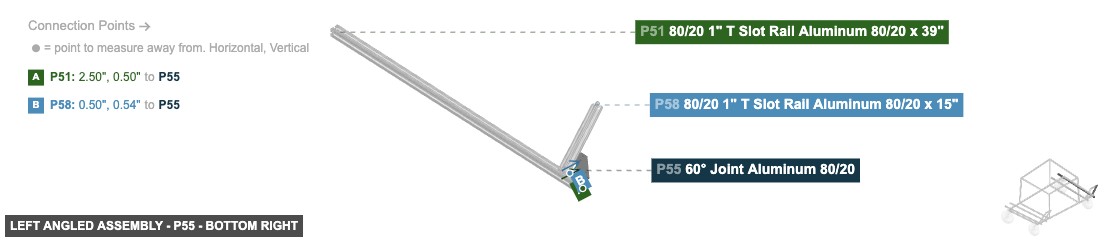
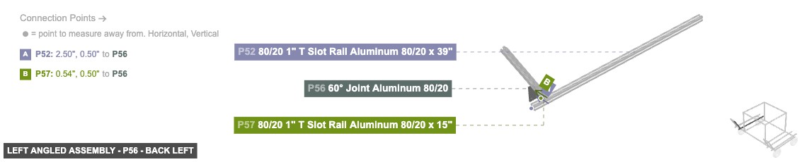
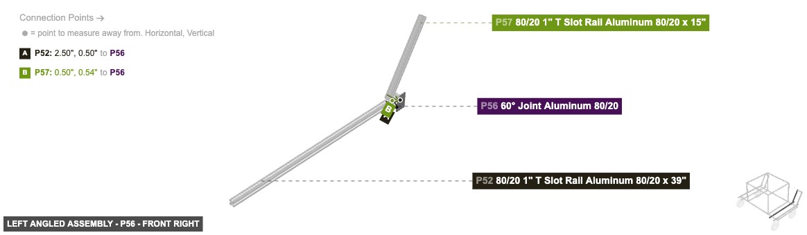
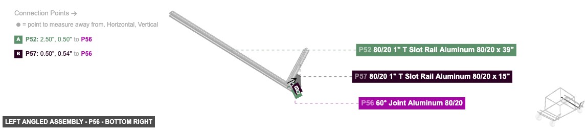
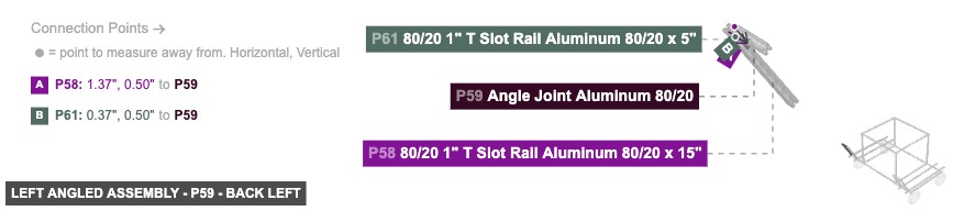
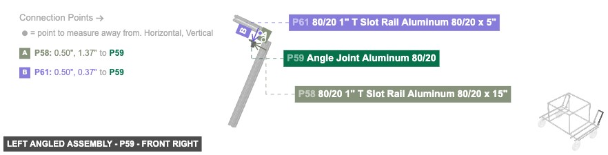
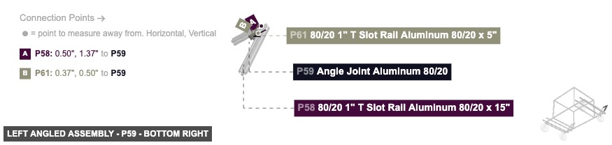
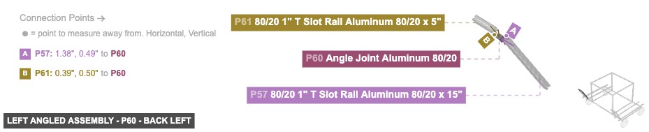
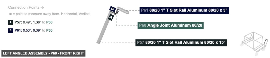
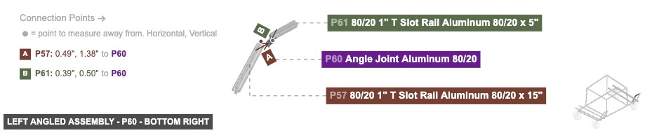
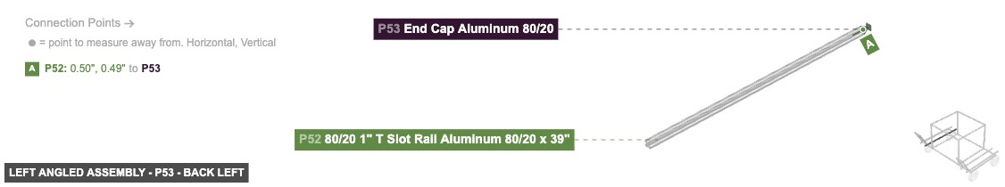
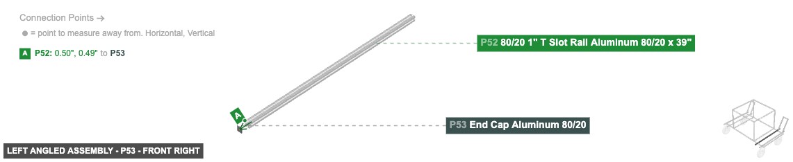
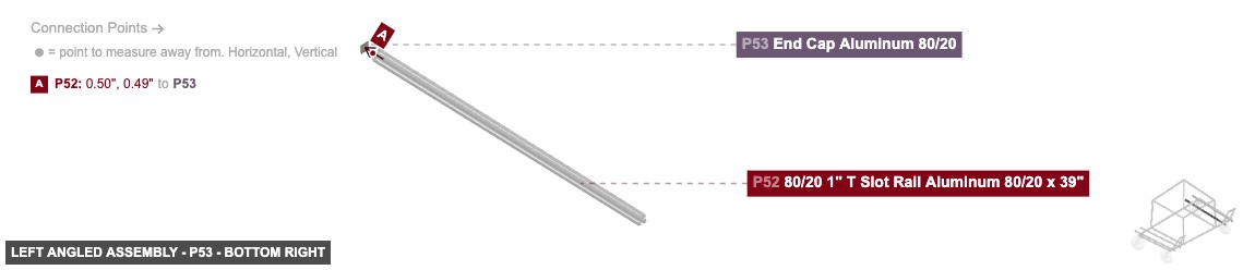
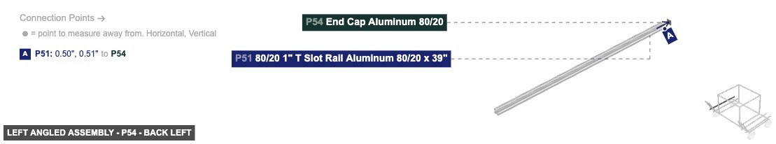
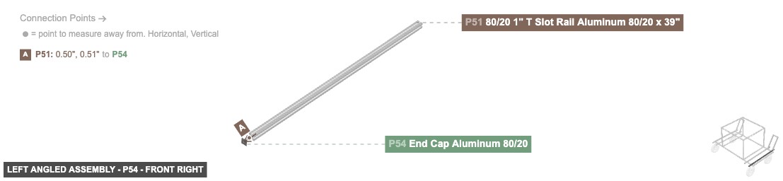
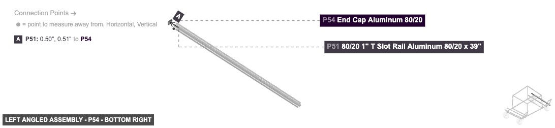
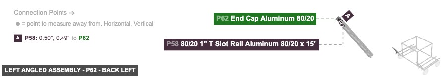
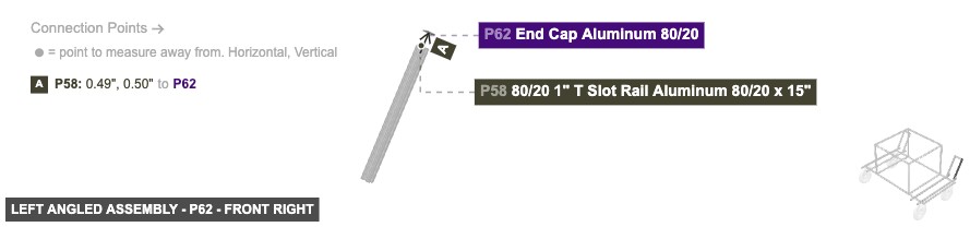
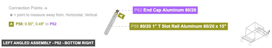
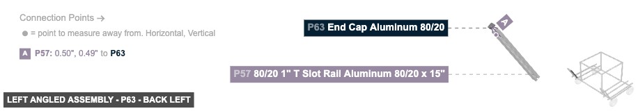
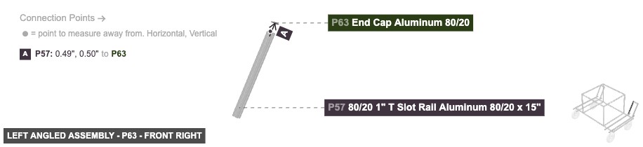
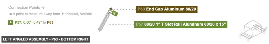
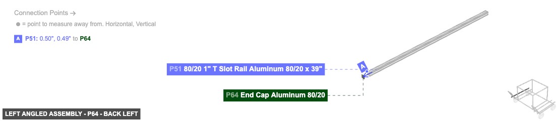
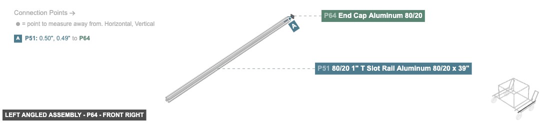
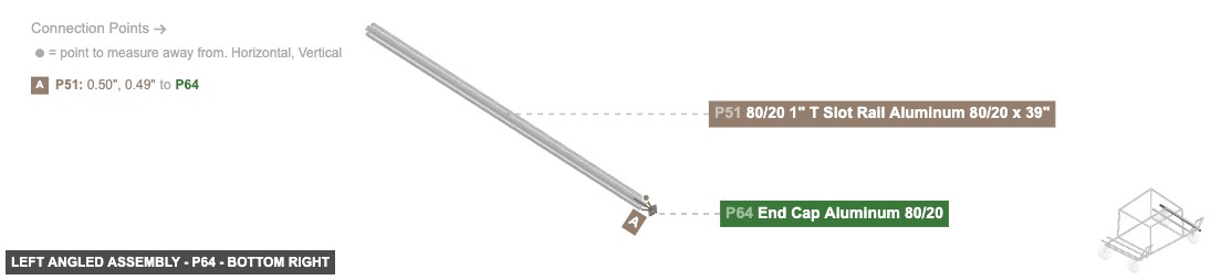
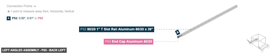
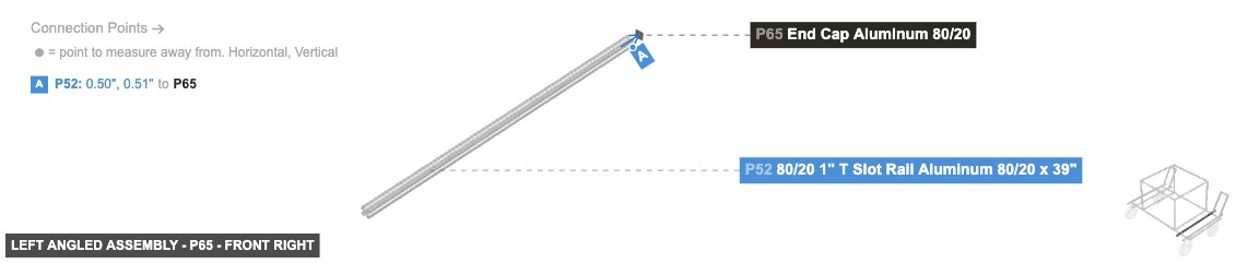
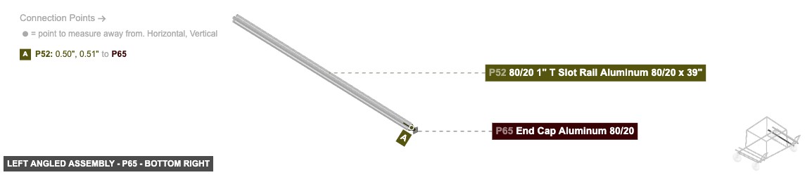
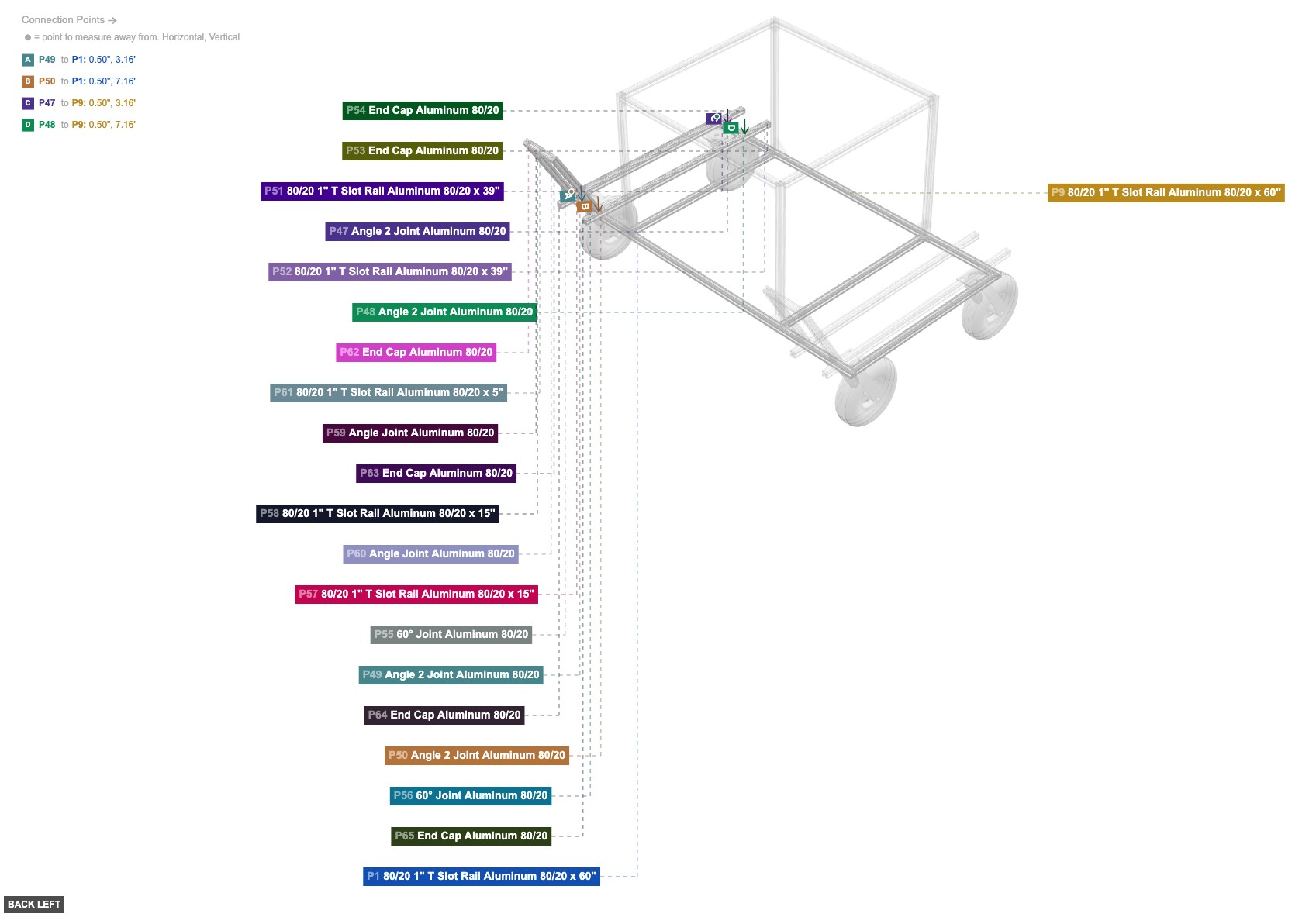
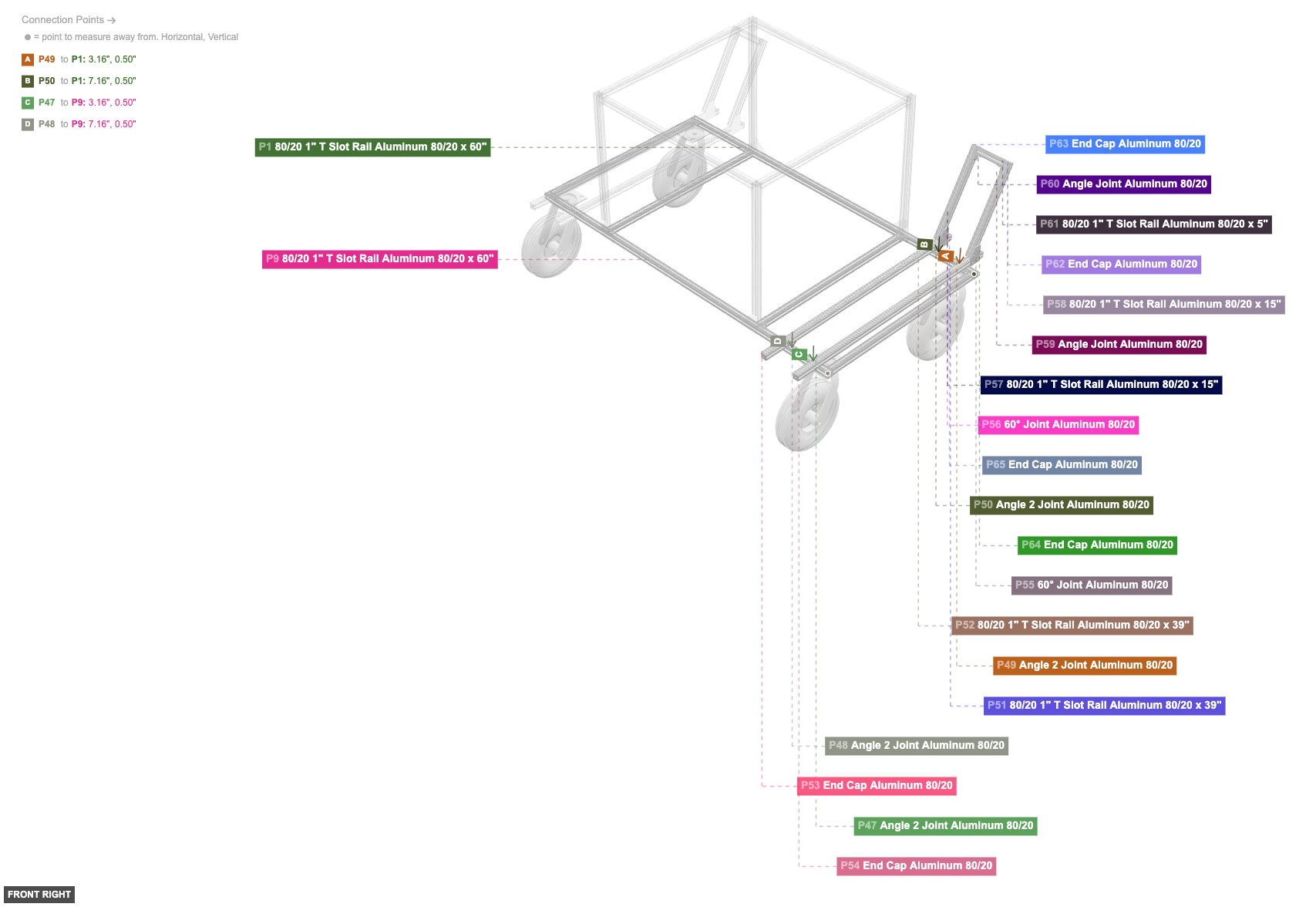
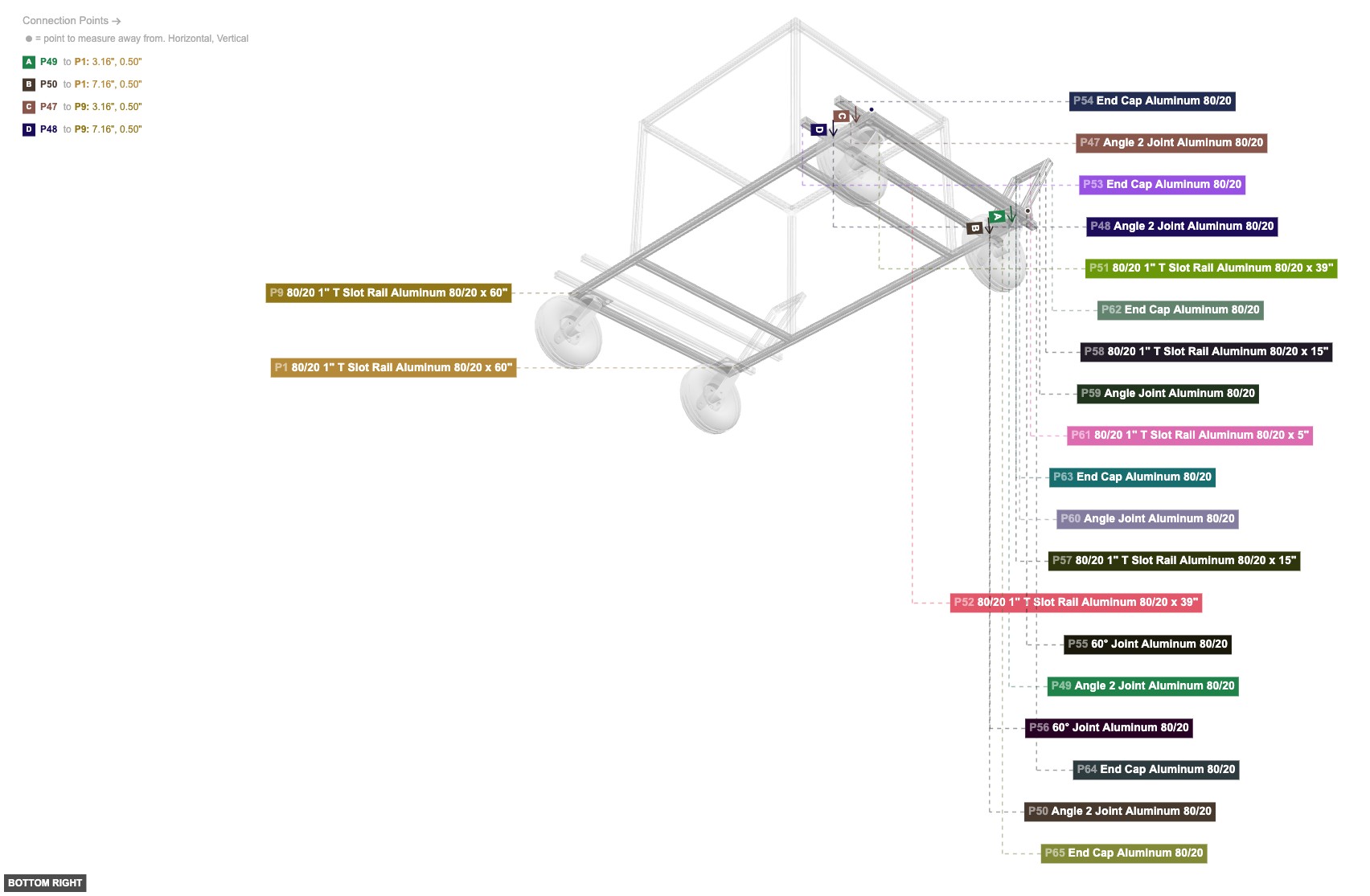
Forms the angled support structure on the left side.
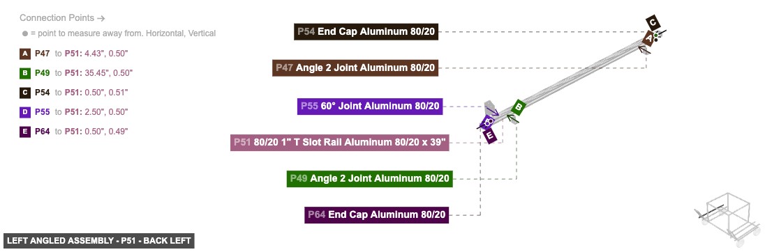
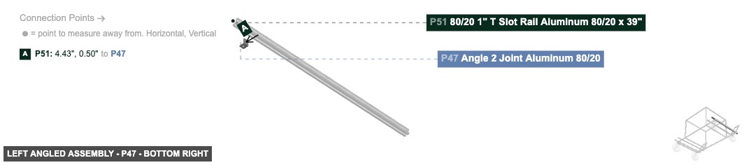
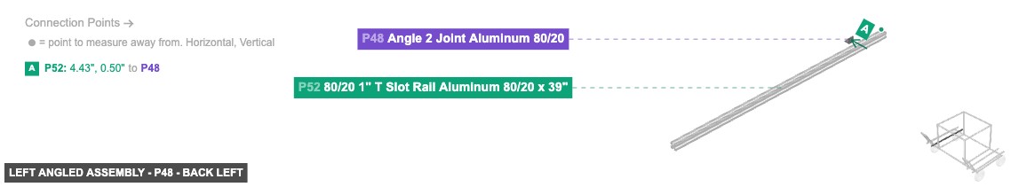
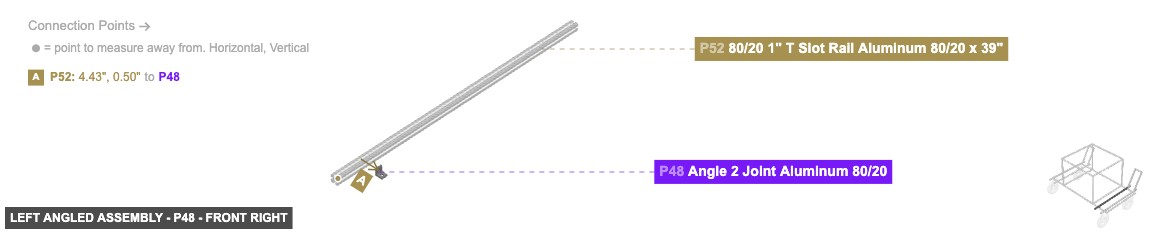
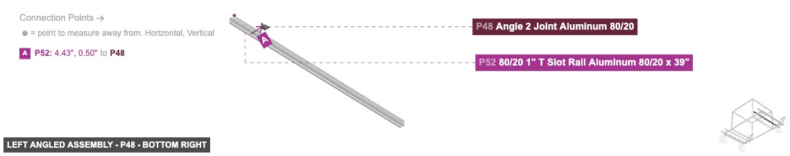
1. Assemble the angled frame: Connect P58 (15" Rail) to P51 (39" Rail) using P55 (60° Joint). Connect P57 (15" Rail) to P52 (39" Rail) using P56 (60° Joint). 2. Connect the top: Attach P61 (5" Rail) between P57 (using P60 Angle Joint) and P58 (using P59 Angle Joint). 3. Prepare base connections: Attach P49 (Angle 2 Joint) to P51's top rail. Attach P47 (Angle 2 Joint) to P51's top rail. Attach P50 (Angle 2 Joint) to P52's top rail. Attach P48 (Angle 2 Joint) to P52's top rail. (Position these joints to align with P1 and P9 from Group 1). 4. Add end caps: Attach P62 (End Cap) to the top End Hole Female of P58. Attach P63 (End Cap) to the top End Hole Female of P57. Attach P54 and P64 (End Caps) to the front and back End Hole Females of P51. Attach P53 and P65 (End Caps) to the front and back End Hole Females of P52.
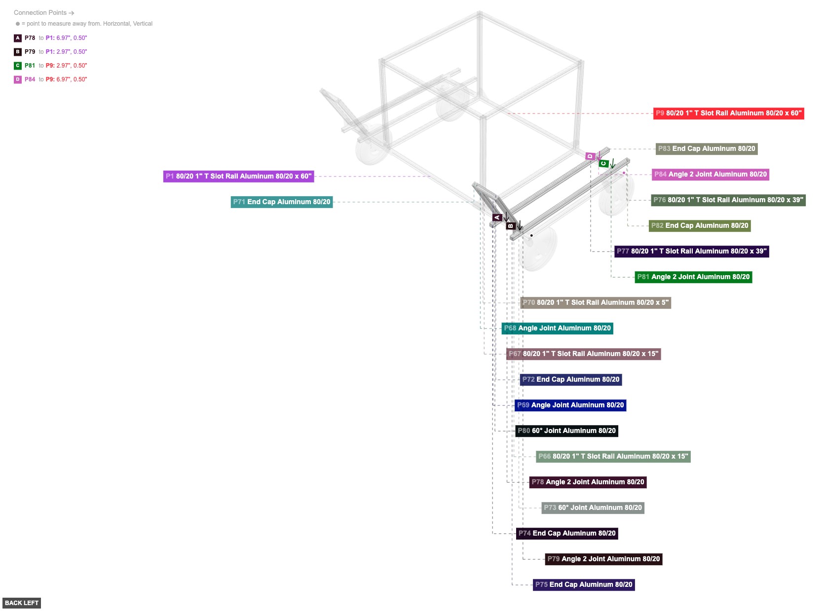
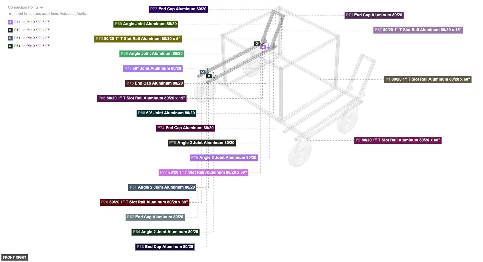
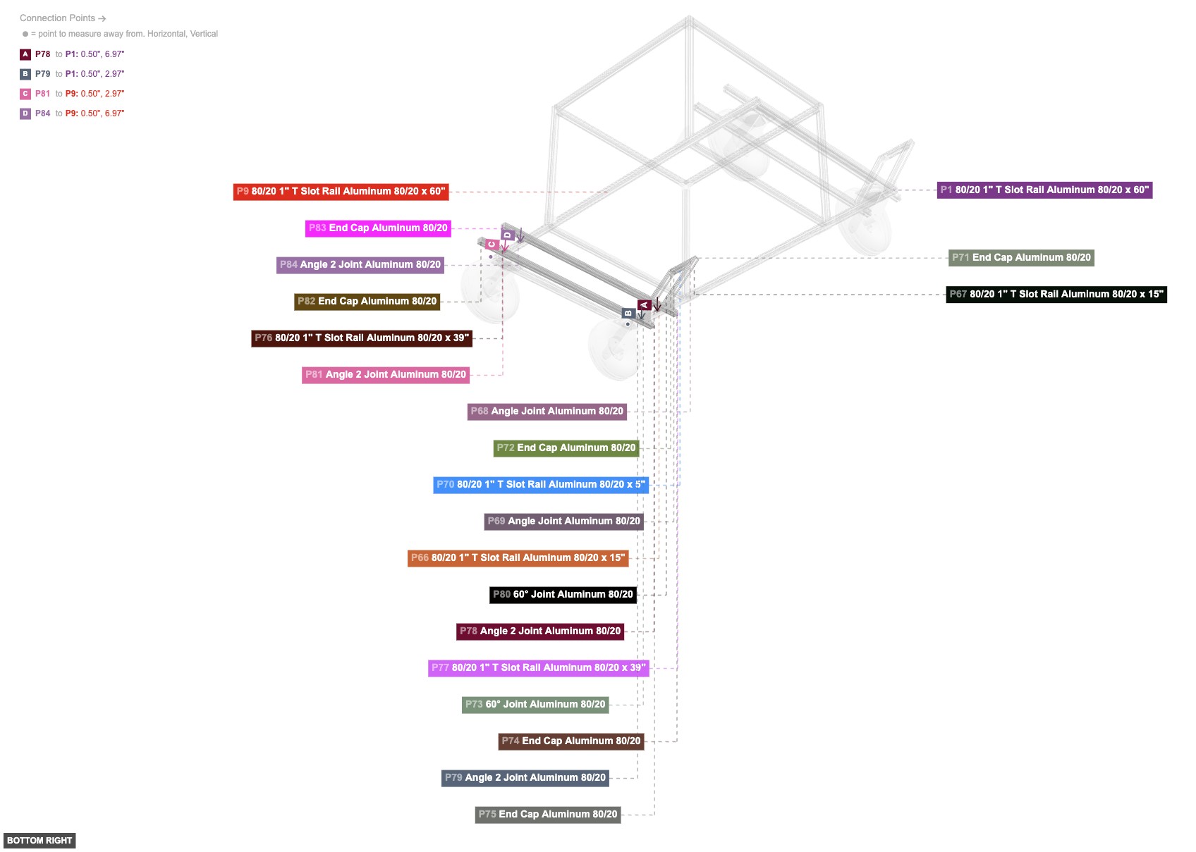
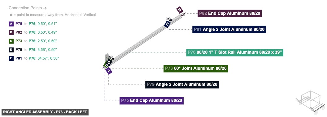
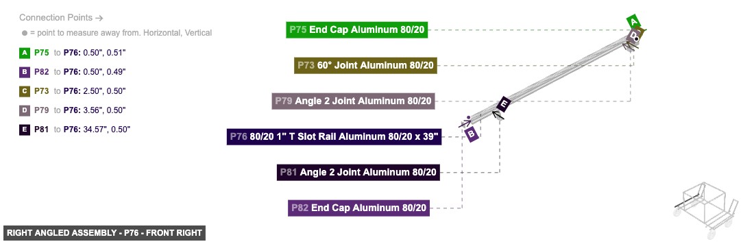
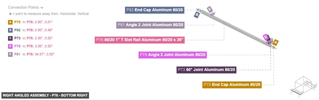
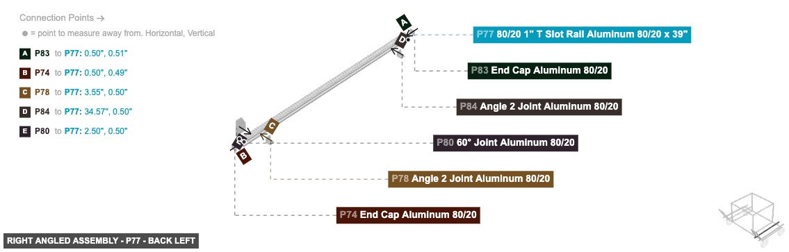
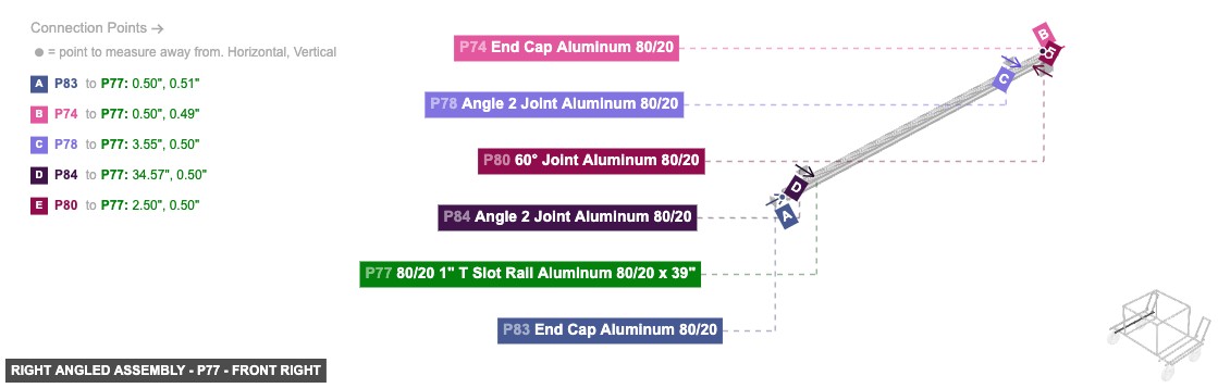
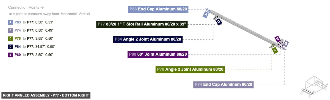
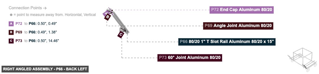
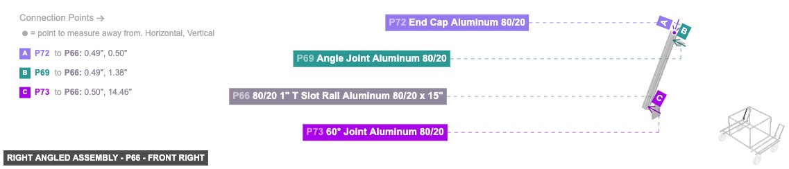
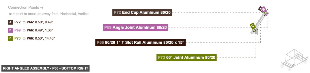
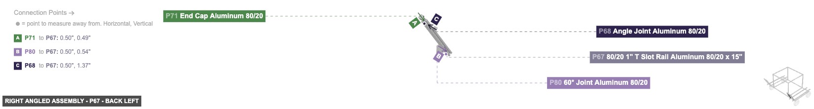
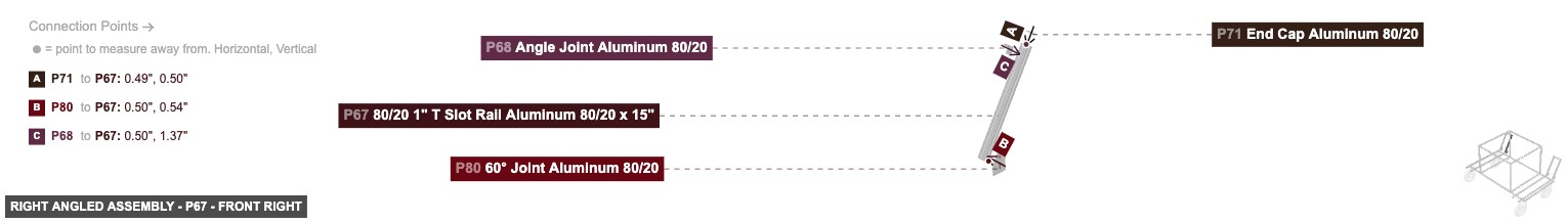
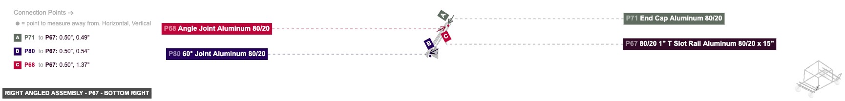
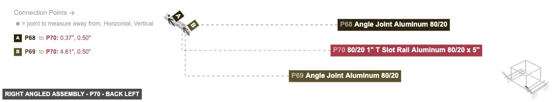
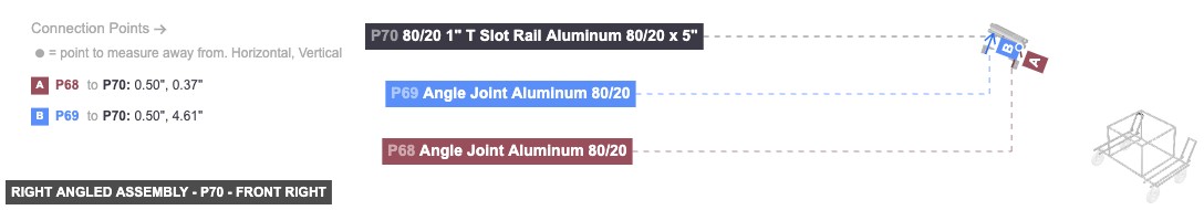
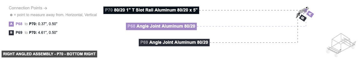
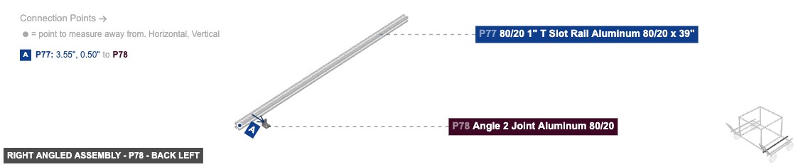
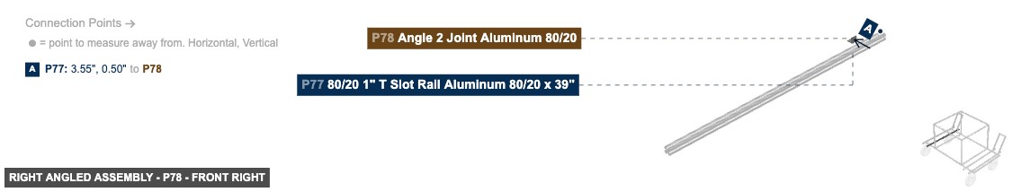
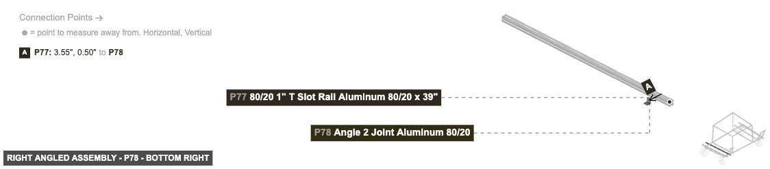
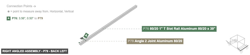
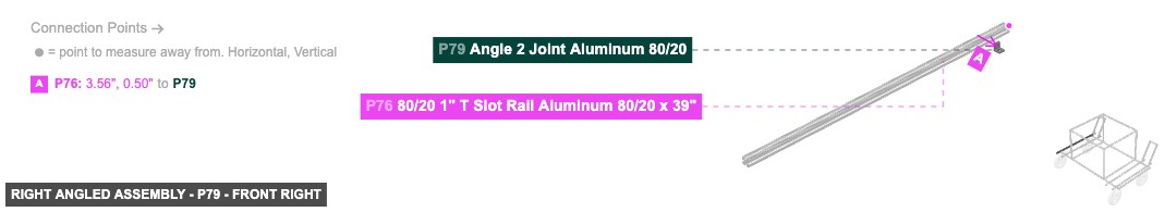
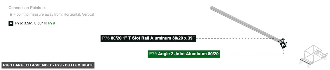
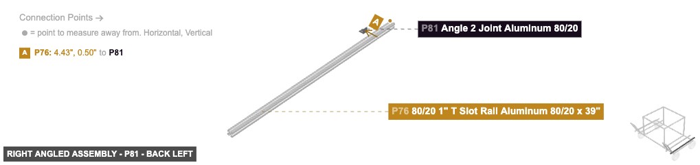
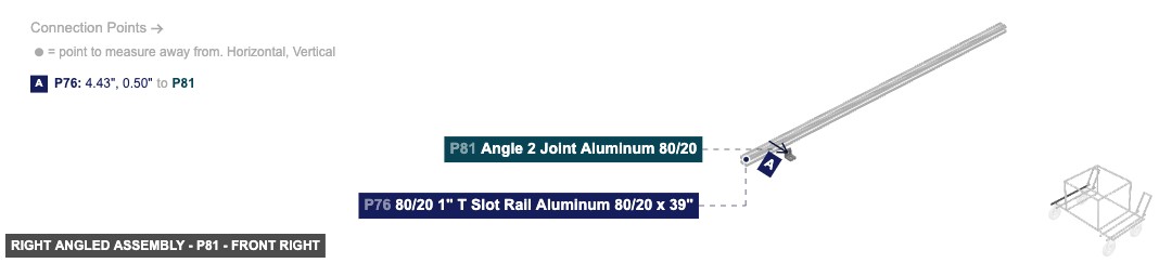
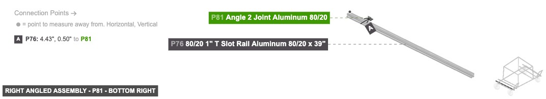
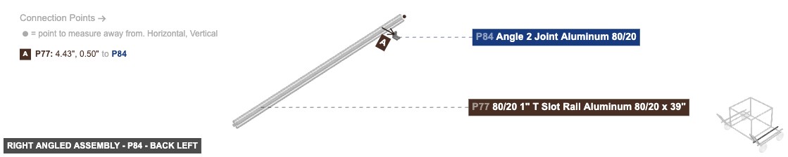
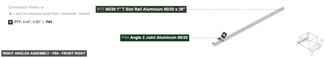
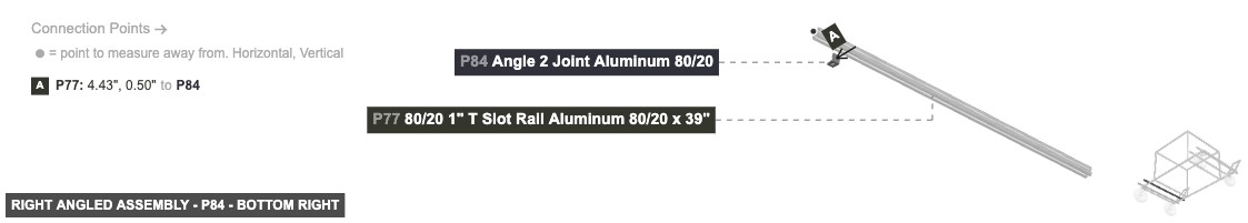
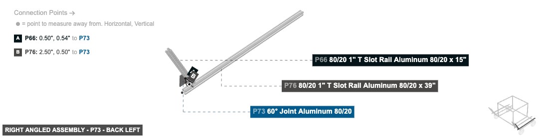
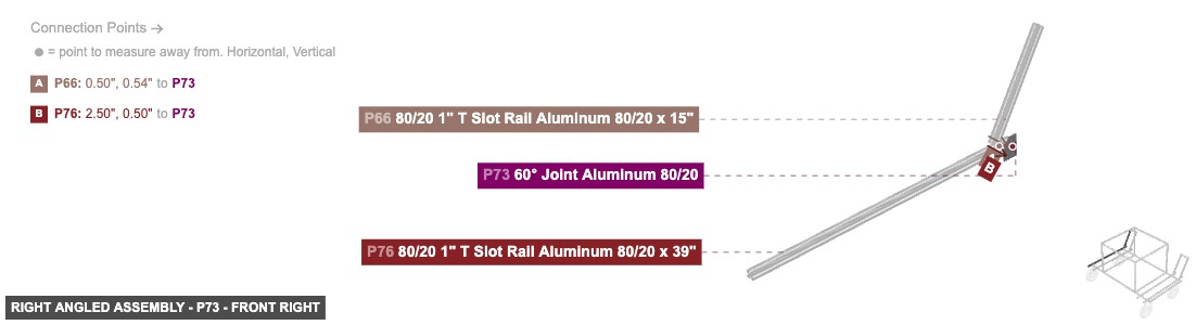
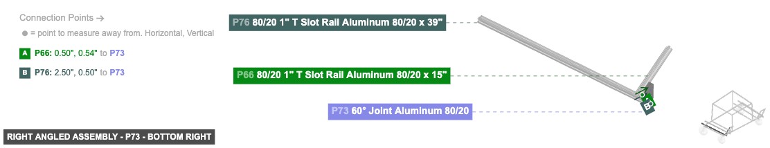
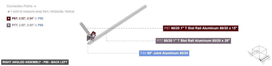
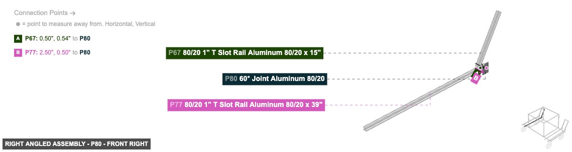
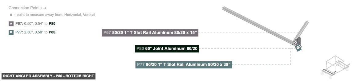
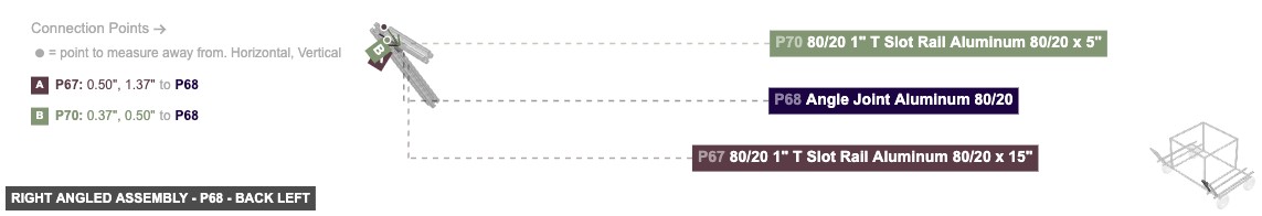
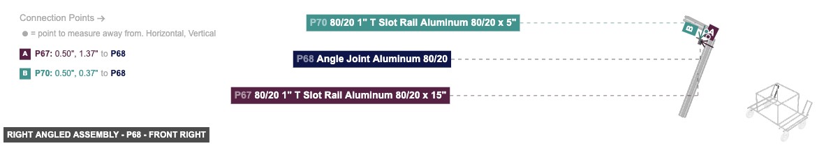
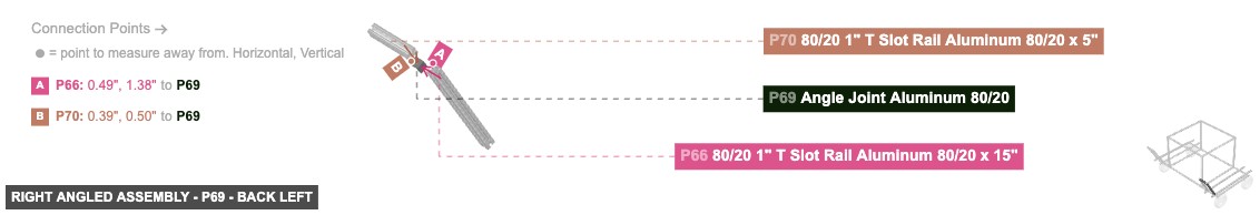
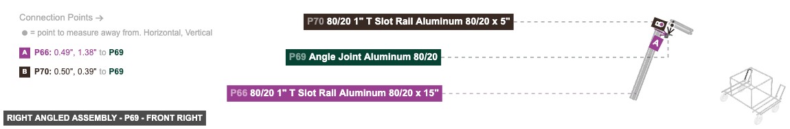
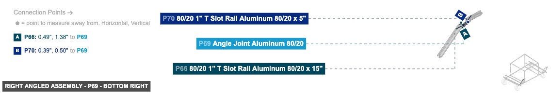
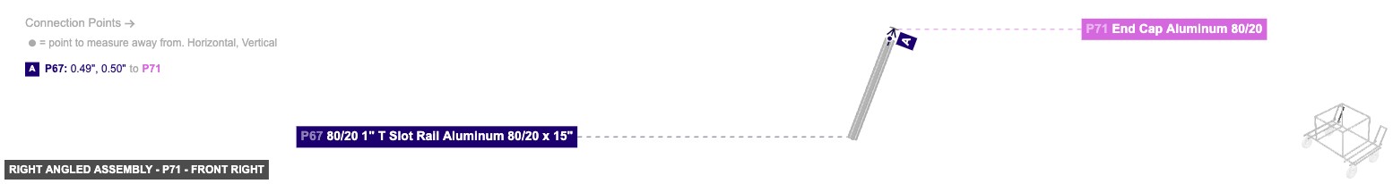
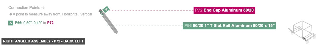
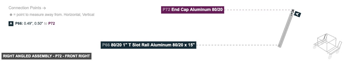
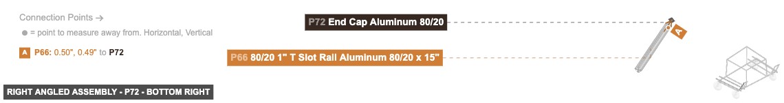
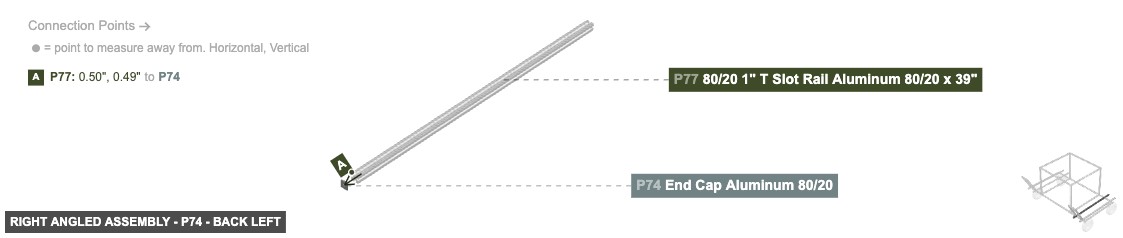
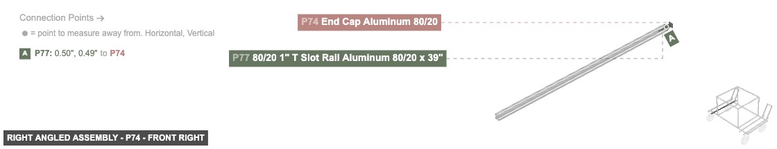
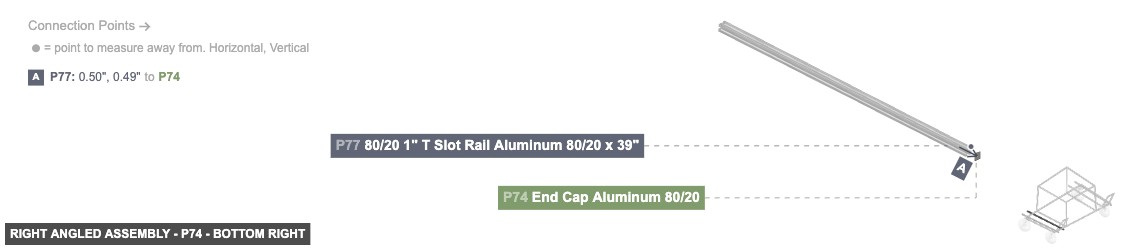
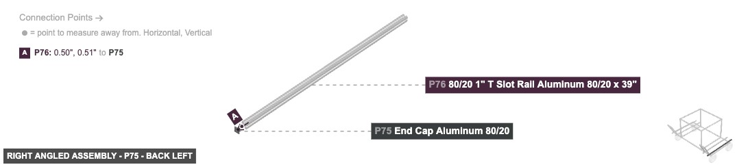
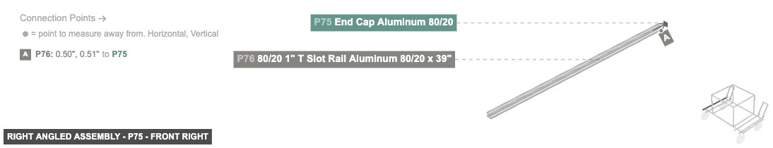
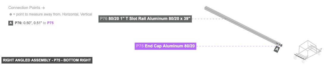
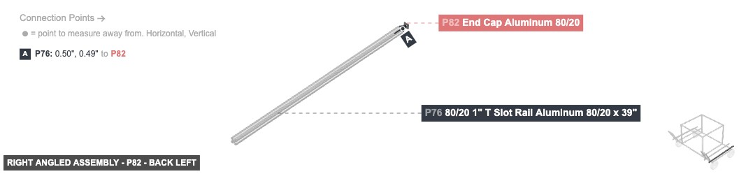
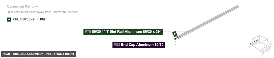
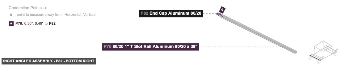
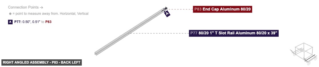
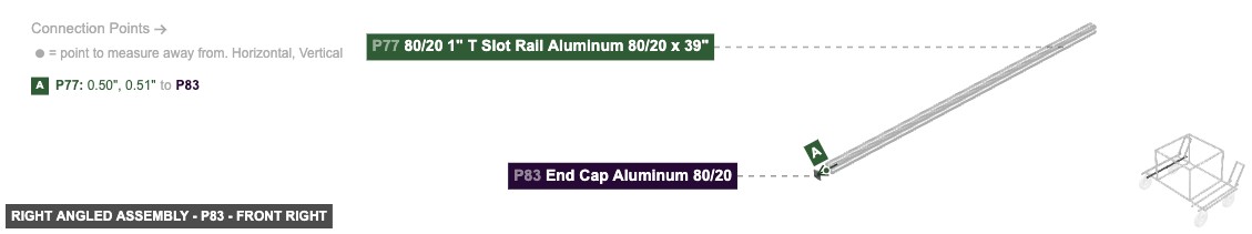
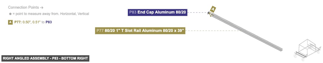
Forms the angled support structure on the right side.
1. Assemble the angled frame: Connect P66 (15" Rail) to P76 (39" Rail) using P73 (60° Joint). Connect P67 (15" Rail) to P77 (39" Rail) using P80 (60° Joint). 2. Connect the top: Attach P70 (5" Rail) between P66 (using P69 Angle Joint) and P67 (using P68 Angle Joint). 3. Prepare base connections: Attach P78 (Angle 2 Joint) to P77's top rail. Attach P84 (Angle 2 Joint) to P77's top rail. Attach P79 (Angle 2 Joint) to P76's top rail. Attach P81 (Angle 2 Joint) to P76's top rail. (Position these joints to align with P1 and P9 from Group 1). 4. Add end caps: Attach P72 (End Cap) to the top End Hole Female of P66. Attach P71 (End Cap) to the top End Hole Female of P67. Attach P74 and P83 (End Caps) to the front and back End Hole Females of P77. Attach P75 and P82 (End Caps) to the front and back End Hole Females of P76.


Forms the bottom foundation of the cart and includes the wheels.
This base frame supports the Main Box Structure (Group 2) and the Angled Assemblies (Group 3 and Group 4).
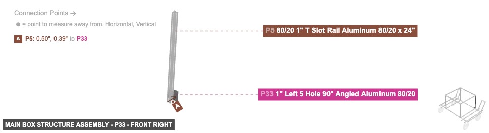
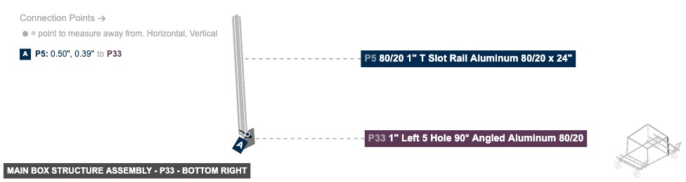
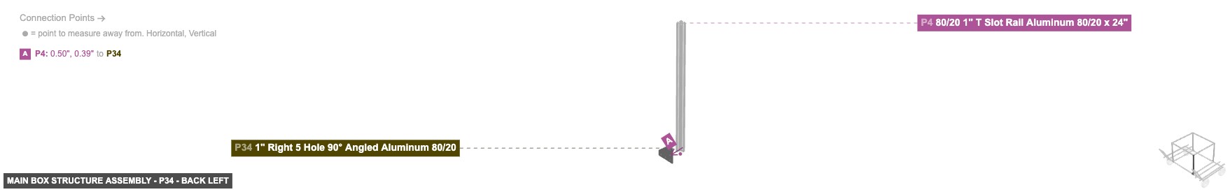
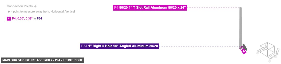
Creates the upper storage area and connects it to the base.
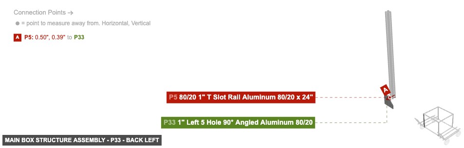
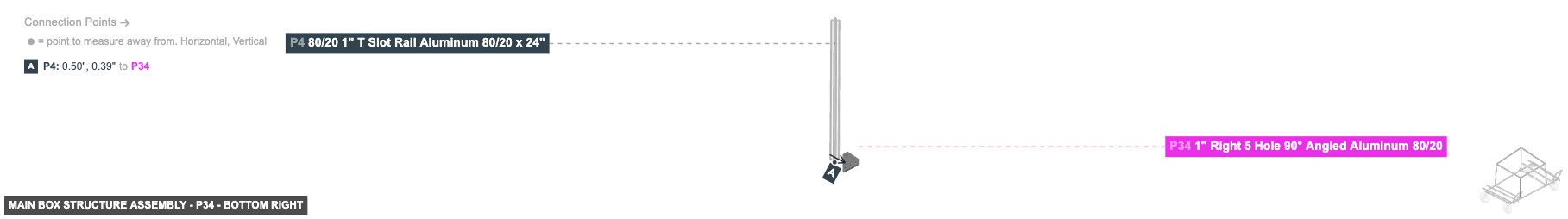
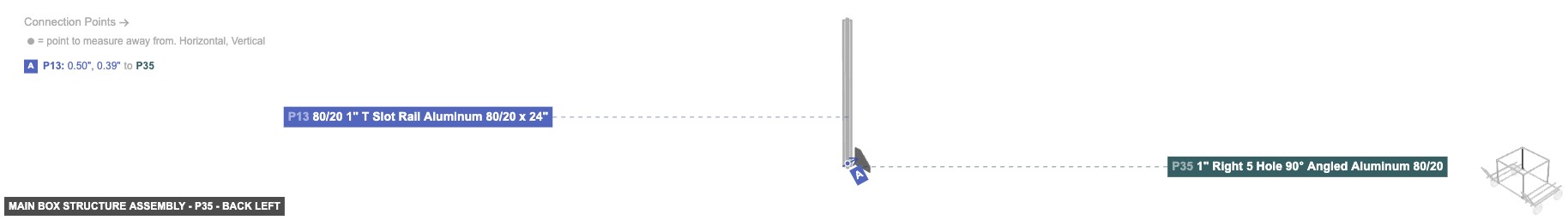
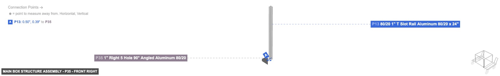
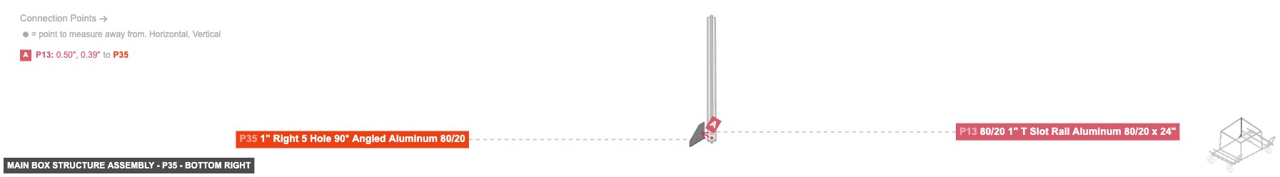
Place the assembled Box Structure onto the Base Frame (Group 1). Secure P5 to P1 using the pre-attached P2 (Angle Joint). Secure P4 to P1 using the pre-attached P3 (Angle Joint). Secure P13 to P9 using the pre-attached P10 (Angle Joint). Secure P12 to P9 using the pre-attached P11 (Angle Joint). Secure the corners using Brackets: P33 (Left 5 Hole Bracket) between P1/P5, P34 (Right 5 Hole Bracket) between P1/P4, P35 (Right 5 Hole Bracket) between P9/P13, P36 (Left 5 Hole Bracket) between P9/P12.
Forms the angled support structure on the left side.
Attach this assembly to the Rolling Base Frame (Group 1). Secure P51 to P1 using P49 (Angle 2 Joint). Secure P51 to P9 using P47 (Angle 2 Joint). Secure P52 to P1 using P50 (Angle 2 Joint). Secure P52 to P9 using P48 (Angle 2 Joint).
Forms the angled support structure on the right side.
Attach this assembly to the Rolling Base Frame (Group 1). Secure P77 to P1 using P78 (Angle 2 Joint). Secure P77 to P9 using P84 (Angle 2 Joint). Secure P76 to P1 using P79 (Angle 2 Joint). Secure P76 to P9 using P81 (Angle 2 Joint).